Lectures and Homework Files & Media Links
All information on one handout
Lab Files & Media Links
| Lab 00 Measurement Review | |||
| Lab 01 Triangle Sketches | Video | ||
| Lab 02 Trial Head | |||
| Lab 03 Displacer Crank | |||
| Lab 04 Test 1 Practical | |||
| Lab 05 Lego Block | |||
| Lab 06 Rocker Arm | |||
| Lab 07 Lego Assembly | |||
| Lab 08 Test 2 Practical | |||
| Lab 09 Earle Model & Drawing | |||
| Lab 10 Stirling Engine Project Due | |||
| Lab 11 Stirling Engine Prints Reassignment | |||
| Lab 12 NX Sheet Metal | |||
| Lab 13 Final Exam Practical |
Unit 1 – Introduction to NX
Lectures
- Part A – Open a File and Use View Controls
- NX 1855 Video (applies through 1980)
- 1A Homework Assignment
- Nothing to Upload for 1A
- 1A Quiz 1855 (applies through 1980)
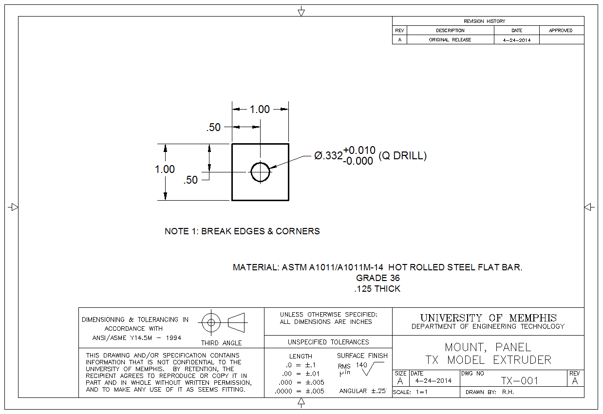
- Part B – Example Model – Panel Mount Model
- NX 1926 Video
- NX 1980 Video
- 1B Homework Assignment
- Create a 3D model of the Panel Mount.
- Name your file as follows: HW01A_uuid.prt (where uuid is your email, not U number).
- Note: All geometry must be fully constrained.
- Upload TWO files:
- Your PRT file (see name format above)
- A SCREENSHOT showing the sketch is properly defined.
- 1B Quiz
- Know when and how units of an NX model are specified.
- Know the process of specifying a destination directory (folder).
- Understand the difference between a U number and a UUID.
- Understand what a sketch is.
- Understand best practices regarding holes and round shapes.
- Understand how to know when a sketch is properly defined.
- Know two ways that a 2D boundary can be used to create a 3D body.
Labs
- Lab 00 – Measurement Review
- Lab 01 – Triangle Sketches