Objective
To demonstrate student ability to build a solid model that accurately reflects pre-defined geometry.
Requires knowledge of coordinate systems, sketching, expressions, constraints, extrusions, revolutions, and Boolean operations, thread design feature.
Assignment
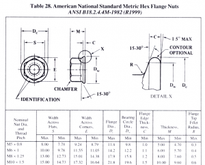
Create a solid model of the Metric Flange nut shown below.
The model you will do is based on your last name.
- a-d: Create model for M5 x 0.8
- e-l: Create model for M6 x 1
- m-r: Create model for M8 x 1.25
- s-z: Create model for M10 x 1.5
Save your work in your directory under a sub-directory named FLANGE_NUT
Any sketches used must be fully constrained, and the model origin 0,0,0 must be the center of the nut on the faying surface.
Your model must use expressions that have the same names as those used in the drawing (A, B, C, etc.).

