Reading Assignment
- 24.1 Introduction to Milling
- 24.2 Fundamentals of Milling Processes
- 24.3 Milling Tools and Cutters
- 24.4 Machines for Milling
Recommended Links
- Study Guide – Milling
- Crash Course in Milling Video Series (Highly recommended)
Outline
Milling Machines
Milling Methods
Peripheral Milling
Also called “slab millling”
Milled surface is parallel to cutter axis
Cuts with the periphery of the cutter
Milled surface is generally at right angle to axis of the cutter.
Should be applied where possible.
End Milling
Other Milling Operations
Straddle Milling
Gang Milling
Gear Milling (see also Gear Hobbing)
Cam Milling
Thread Milling
Holemaking
Tapping
Up and Down Milling
Main difference is in the cutting forces generated.
- Up milling opposes the thrust force, requires more feed force.
Advantages of Down Milling
- As opposed to up milling, down milling cut begins with a nonzero depth of cut (increases tool life)
- Welded chips break off
- Forces table down, creates less vibration.
- Feed drive power consumption lower
- Throws chips down instead of up
Milling Cutters
End Mill Geometry
- Flutes
- Flute length
- Cut length
- Rake angle
- Helix angle
- Relief angle
Machining Parameters
Speed
The distance the cutting edge of the cutter travels (fpm) each minute.
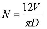
Convert Cutting Speed to rpm.
- V = cutting speed in fpm (Mach. Hndk).
- D = tool diameter in inches
- N = RPM
Feed Rate
Note! Spindle speed does not affect the feed rate.
fm = ft x nt x N
Where fm = Feed Rate in inches/min (not inches per revolution)
ft = Feed per tooth in inches
nt = Number of teeth on the cutter
N = Cutter rpm
Depth of Cut
- Axial
- Radial

