See also:
Coordinate Systems
Rectangular Coordinates
Diameter Coordinate System
Polar Coordinates
Coordinate Systems
Rectangular Coordinates
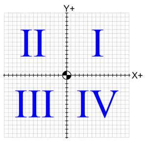
Most people are familiar with the rectangular (or Cartesian) coordinate system. This system of coordinate planes uses real number lines arranged at right angles to allow any point in space to be clearly and unambiguously determined. In mathematics, the order of the coordinates (separated by a comma) designates a point on the graph. For instance (2,3) would designate a point with an X value of 2 and a Y value of 3. The syntax for this point is very similar in G-Code programming. This will be discussed later in this chapter.
The sign of each coordinate (whether it is positive or negative) is just as important (if not more important) as the value. For example, (3,2) is nowhere near (-3,-2). It is helpful to position the coordinate grid such that it the programmer only needs to work in one quadrant. The coordinate plane (the XY plane) divides neatly into four quadrants. In the first quadrant (I) , both coordinates are positive (+,+) in the second (II), the X coordinate is negative, but the Y coordinate is positive (-,+). The other two quadrants, III and IV, work in the same way. Working in a single quadrant will help eliminate errors. When this is not possible, at least try to position the grid so that the origin is a place that would be obvious to an operator or other programmer.
This system of planes can be overlaid on top of a machine table or workpiece to enable the machine to be directed to any point on the workpiece or machine table. In the figure below, the programmer has oriented the coordinate system so it is aligned with a particular workpiece to be cut. Since all the cutting will take place in the First Quadrant (I), the program will have all positive X and Y values when the tool is over the part.
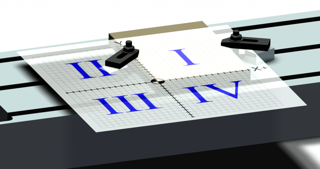
It is the ease at which a set of Cartesian coordinates can be converted into machine-readable numbers that allows CNC to be really quite easy to program.
These coordinates correspond with machine axes. Primary linear axes are X, Y, and Z.
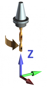
One of the first steps in programming is to be able to identify the axes of motion on the machine tool you are programming. As a general rule of thumb, the Z axis is the direction of motion that is along the axis of spindle rotation.
On a milling machine, finding the Z axis is pretty intuitive. The spindle rotation (whether it is clockwise or counterclockwise) is parallel to the Z axis. The depth of a drilled hole is usually determined by a Z coordinate.
On a lathe it may be a little less intuitive, but the rule still holds. On a lathe the workpiece is mounted in the spindle by means of a chuck or other workholding device. The axis that the spindle rotates around is the Z axis. A typical two-axis lathe would have X and Z axes. The X axis corresponds to the diameter of the workpiece, and the Z axis corresponds to where the tool is located along the length of the workpiece.
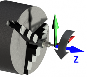
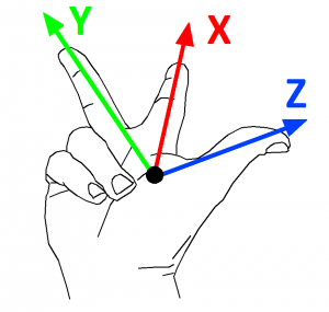
After finding the Z axis, the X axis is usually the easiest to find. Most of the time, the X axis is parallel to the floor. The X axis will be orthogonal (at a right angle) to the Z axis. Finally the Y axis will be at a right angle to both the X and Z axis. The orientation of these three axes follows what is known as the right hand rule. If you orient your right thumb with the Z axis, the X and Y axes can be aligned with your index and middle finger respectively. The tips of your fingers will be show the positive direction of each axis.
Bear in mind that we have only discussed the direction of the axes and how they are oriented with respect to each other. The major point that we have not talked about is where the origin is for these coordinate systems. This will be discussed later in this chapter under G54-G59 – Work Coordinate System Offset (page).
Diameter Coordinate System
A special kind of rectangular coordinates are diametral or diameter coordinates. Diameter coordinates are rectangular coordinates, but one axis (such as the axis of the cross slide of a lathe) is given in diameters rather than in an absolute distance from the origin. Lathe toolpaths are most commonly programmed using diameter coordinates.
A common lathe program would require cutting a profile in the Z, X plane such as the one pictured in Figure 4. The coordinates of points 1 through 3 would be as follows:
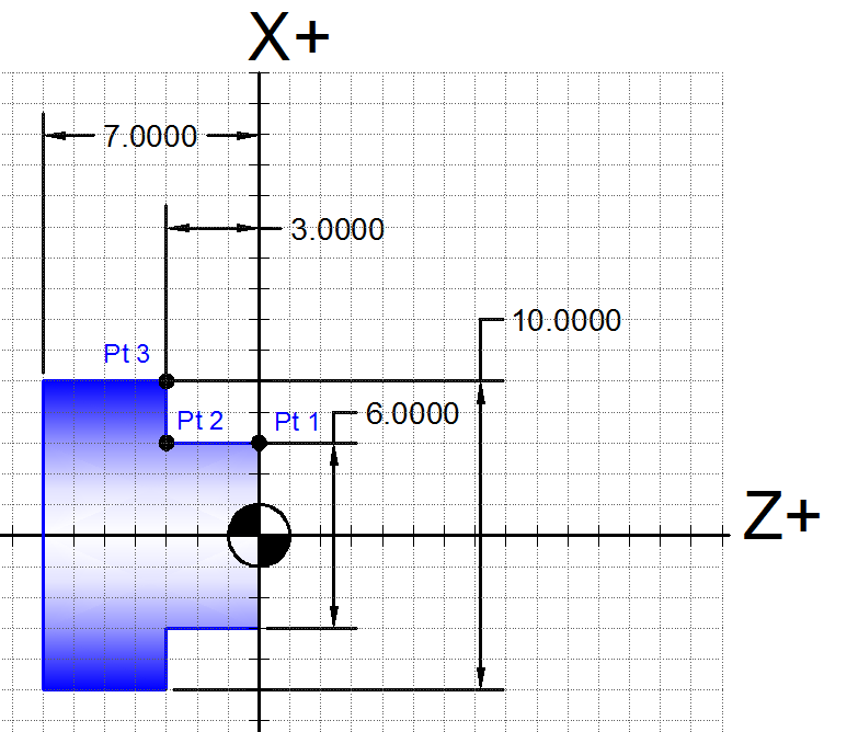
Notice this is different from an ordinary rectangular coordinate system with respect to how the X values are found. For instance, an ordinary coordinate system would assign point 1 an X value 3.0 but a diameter coordinate system assigns a value of 6.0. This may seem unusual at first, but it is useful for programming a lathe because one axis always determines the diameter of round parts.
Polar Coordinates
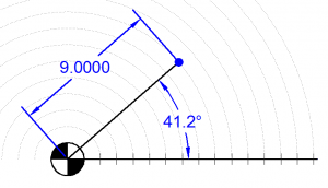 Polar coordinates define points by giving their angle (from a base line) and a distance from a particular point. Polar coordinates are commonly used to describe a circular array of holes, such as a bolt hole circle. Polar coordinates can be converted to rectangular coordinates by trigonometry as shown below (for a review of basic trigonometry, see Appendix A – Foundational Mathematics).
Keep in mind that polar coordinates are not the same thing as diameter coordinates.
Absolute Vs. Incremental Coordinates
Coordinate System Video

