Step 1 – Eliminate Assumptions
Step 2 – Establish The Coordinate System
G54-G59 – Work Coordinate System Offsets
T and H – Tool Numbers and Length Offsets
G90 & G91 – Absolute Vs. Incremental Coordinates
G20 or G21. 25
Step 3 – Program Toolpaths
M03, M04, and M05 – Spindle switch
G00 – Rapid Move
G01 – Linear Cutting Move
G02 and G03 – Arc Cutting Move
Lathe Movements
Writing a CNC Program
There is little room for error when writing CNC programs. There must be complete agreement between what a programmer thinks is going to happen and what the machine tool actually does. CNC equipment is expensive, and it is powerful enough to destroy itself if programmed improperly. That said, if a few simple steps are followed consistently, the chances of making an error can be minimized.
Be sure to read and understand the machine tool maker’s documentation for the machine you are going to program. If there is inconsistency between this book and the manufacturer’s documentation, the manufacturer’s documentation takes precedence.
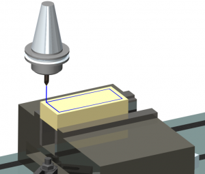
We will use a simple machining example to go through the process of writing a simple program. We will use a pointed engraving cutter to cut a light rectangle into a piece of aluminum. The workpiece will be 2 inches wide by 1 inch tall by 4.5 inches long. It will be mounted in a vise as shown in the figure to the right. The rectangle will be 4.0 x 1.5 (it will be offset 0.250 inches from the perimeter of the workpiece). The depth of the engraving cut should be 0.020 inches deep. The tolerance of the rectangle itself is +/- 0.010 and the position tolerance of the rectangle on the block is +/- 0.050.
Step 1 – Eliminate Assumptions
Because of modal commands (discussed in Chapter 2), it is possible that the machine may have settings in a different state than the programmer may expect. For this reason, all of the settings that could result in unsafe or unintended motion are set explicitly in a program header.
What actually goes into a program header depends on the type of machine tool, product line variation, and company programming standards. Below is a typical program header for a 3-axis milling machine.
N010 (***BEGIN HEADER***);
N020 (DESCRIPTION: PART NUMBER U23-0020 REV C, MILL TOP SIDE);
N030 (SEE SETUP DESCRIPTION ON PROCESS ROUTING SHEET);
N040;
N050;
N070 G17 G20 G40     (XY PLANE, INCH MODE, CANCEL CUTTER COMP);
N080 G55 G80 G90 G94 (ORIGIN, CANNED CYCLE CANCEL, ABS., FEED PER MIN.);
N090 G43             (TOOL LENGTH COMPENSATION ON);
N100;
N110 (***END HEADER***);
This header contains comments to the operator and setup personnel. Remember, the comments and whitespace are completely ignored by the controller. They merely spell out in English what the program is
What is most important here is the bit of code from line N070 to N090. Each of the commands in these blocks will be explained later, but for now it is a good idea to have a general idea of what the commands are doing.
- G17 – Selects the plane in which arcs will be made. G17 tells the controller to make arcs in the XY plane.
- G20 – Sets the units to inches.
- G40 – Cancels cutter compensation. Cutter compensation changes the position of the tool based on its diameter.
- G55 – Tells the controller where the origin (0,0,0) is.
- G80 – Cancels canned cycles. Canned cycles are a way to perform lots of steps by a single command.
- G90 – Tells the machine to use absolute coordinates.
- G94 – Feed rates are in units of distance per minute. In this case, it is inches per minute.
- G43 – Turns tool length compensation on. This will allow the programmer to use tools that are different lengths.
Obviously, there is more to these commands than we discussed here. The important thing to know at this point is how important this header information is. Different companies will have different requirements for program headers for different machines and setups, but the one given above is typical for a milling machine.
At this point, we will be able to start to build a program. If a command that was set in the header given becomes relevant to the program we are writing, it will be discussed in more detail.
Step 2 – Establish The Coordinate System
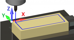
When writing a program, the programmer needs to know how he or she will be able to align the coordinates system(s) of their program with the coordinate system of the machine. In this case, we will use the upper left corner of the workpiece as our work coordinate system. Notice this puts our work in the fourth quadrant. All of our X values will be positive and all of our Y values will be negative. Our Z axis origin is located at the top surface of the block. This will give all our cutting depths negative Z values. I have chosen to use the forth quadrant because of the type of workholding I am using. Our work is being held in a vise that has one fixed jaw and one movable jaw. If I locate the origin on something more or less permanent, I won’t have to go through the as many steps when I tell the machine tool where to put the origin each time.
It is worth noting that the programmer has the choice of where to locate the origin, but little choice over the direction of the axes. These are established by the physical arrangement of the machine.
Now that we are satisfied with the location of our origin, we need to let the machine know where it is. This will be done setting the work coordinate system offsets.
G54-G59 – Work Coordinate System Offsets
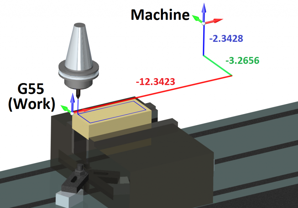
Each machine tool has built into it a coordinate system that is defined by the geometry of the machine. The machine “knows” where it is within its own coordinate system by a series of limit switches and encoders that are located on each of the axes. When they are powered up, most machines go through a homing cycle in in which they move each axis until it hits a limit switch. The coordinate system that is built into the machine is called the machine coordinate system.
A CNC program could be written that uses the machine coordinate system, however this would not be practical since the machine coordinate system has an origin that is nowhere near the workpiece. Fortunately, it is easy to define a coordinate system that aligns with the work to be machined. This is most easily done by defining a work coordinate system(s) by the use of the G codes G54 through G59. Sometimes work coordinate systems are defined relative to some permanent or semi-permanent fixture (such as a vise) attached to the machine table. Other times a work coordinate system is defined relative to a particular workpiece after it has been loaded into the machine. The second method is more common for a job shop or “one of a kind” production run.
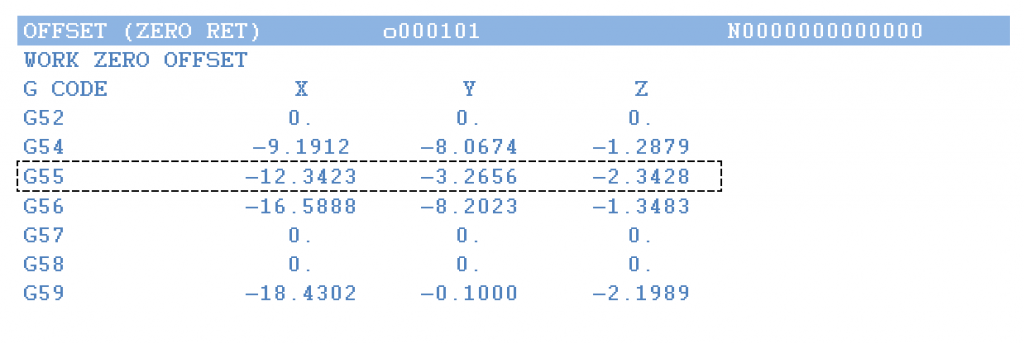
The easiest way to use work offsets is to store them in the offset register. This is done by positioning the machine at the exact place where the desired coordinate system origin is and having the machine record the distance between that point and its own machine coordinate system. A typical offset register screen is shown below. The controller records the distance the machine is from its home position in the register that is displayed on this screen. Notice each row has a corresponding “G Code.” This code is how the programmer uses the work coordinate system origin stored in the register. The values for X, Y, and Z that are on the screen are the distances between the machine origin and each work coordinate system origin.
With the offsets defined in the offset register, the programmer can now make use of the coordinate system origin of his or her choice. When using this method, there is no need to enter the actual distances between the machine and work coordinate system origins into the actual program. All the programmer needs to enter is the G code that corresponds to the correct offset (in this case, we will be using G55).
T and H – Tool Numbers and Length Offsets
Just as important as knowing the coordinate system origin is knowing where the tool is and how long it is. Notice that the Z axis location will be different if we use different lengths of tools.
Mills use a separate tool and tool offset address, for example: T03 H03
Lathes use the T address to specify both tool number and offset.
Note: Calling a tool address does not change the tool! That is done with an M06.
Lathe Tooling Offsets
G90 & G91 – Absolute Vs. Incremental Coordinates
Mile or mile marker.
G90 and G91
G20 or G21
Select the Units
Step 3 – Program Toolpaths
M03, M04, and M05 – Spindle switch
G00 – Rapid Move
G01 – Linear Cutting Move
G02 and G03 – Arc Cutting Move
Lathe Movements
Diameter coordinate system
Step 4 – End Safely
M30
Raise Tool out of the way. Be safe for power up.

Thanks for your explain
Useful information. Thanks
Useful & informative . Easy to understand for beginners . I also write similar article on my site.”cncknowledge.in”
Very usefulness information tq dude