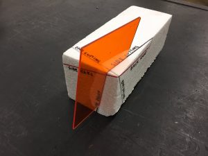
You will be given an ANSI Tool signature and a 1.5 x 1.5 x 4″ piece of PVC.
Using the given code, layout and cut (with a hacksaw) a model of this tool.
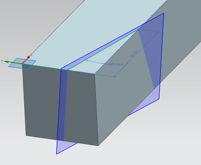
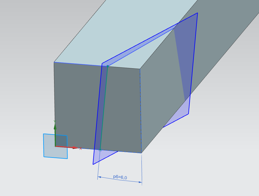
Then, using a 3D CAD program create a solid model of a single point cutting tool shown below. Create expressions that reproduce the variables of the ANSI tool signature shown below. The body of the tool should be .500 x .500 x 3.0. Assign the values given in the diagram.
Notice that the ground tool has three faces that are at compound angles. A possible strategy might be to model two lines that define each of these planes. Then create a datum plane defined by these two lines. You can then trim body with these planes, or draw a sketch on the planes and extrude/subtract. Think of simulating the grinding of a cutting tool.

pls send me tool signature of drill