Recommended Reading:
Objectives:
- Familiarize students with the the purpose and function of a CMM machine
- Develop an understanding of how CMMs define point geometry
- Reinforce spatial visualization skills
- Introduce students to the Dimensional Measuring Interface Specification (DMIS) language
- Introduce students to PC-DMIS software
Materials
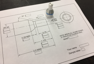
- LATHE REVIEW INSPECTION PRINT
- Workpieces from TECH 4571
Procedure:
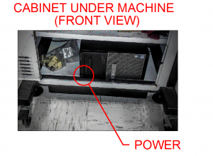
- Power up PC
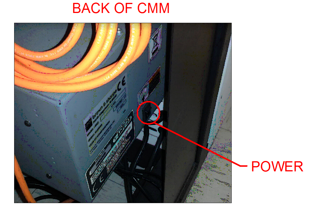
- Power up CMM
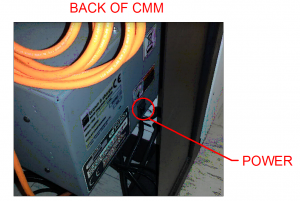
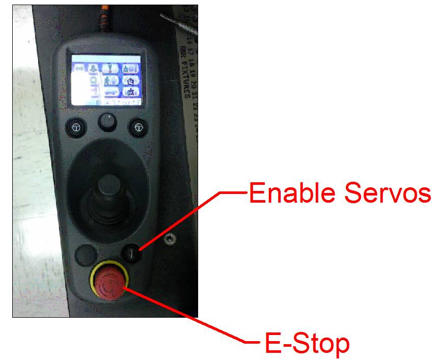
- Make sure the E-stop is out by twisting it gently.

- Start the servos by pressing the “Enable Servos” button.
- Hold it down until you hear the a “click.”
- Be sure your tool stack looks like the photo below and the probe points straight down.
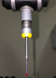
If it does not, SEE YOUR INSTRUCTOR. - Start PC-DMIS.
- You will need to click “yes” at the dialog box that appears.
- Start a new program.
- Be aware that PC-DMIS defaults to opening an existing file. Cancel this dialog box.
- Name your file YOURUUID_4476_1
- Note: UUID is Not your U001234 number.
- Select INCH units.
- Select “4476 Probe”
- Click OK to home the machine
- Jog the machine by holding either “T” button on the pendant while jogging the joystick.
- USE “TURTLE MODE” when within 3″ of the part.
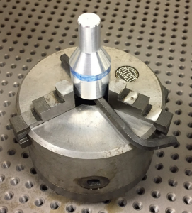
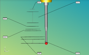
- Ensure that the part is set up as shown here:
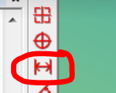
- Enable the “Measured Features” toolbar.
- Select “Measured Guess” mode.

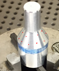
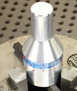
- Probe five points on the end of the small cylinder. Avoid the stamped letter.

- Press “ENTER” on the teach pendant.
- You should hear a chime.
- A plane entity should appear in the DMIS program.
- Rename this plane to END PLANE.
- Now probe a series of 10-15 points on the small cylinder as shown:

- If guess mode creates an entity other than a cylinder, delete all the points (and the entity) and re-probe.
- Rename this cylinder to “SM CYL”
- Probe the cone shape with 10-15 points as shown:
- Rename this element CONE.
- Probe the large cylinder with 10-15 points.
- Rename this cylinder LG CYL
- Create a constructed circle between the large cylinder and the cone:

- Rename this circle “CIRCLE.”
- Create an alignment
- Name the alignment AL1
- Position the alignment such that it is
- LEVELED on the CIRCLE
- ROTATED to the SM CYL
- Origin on on the CIRCLE
- You should notice the probe now appears in the display with your geometry.
- Create a distance dimension between CIRCLE and END PLANE.
- Verify other dimensions , such as angle of the cone, and the diameters of the cylinders.
- Write the actual dimensions on the inspection sheet.