Objective
Design, build and test functional injection mold – This lab counts as three lab grades.
NOTE 1: Keep it simple. Small details (except engraving) will not work well. They require very small tools and lots of time (we have neither).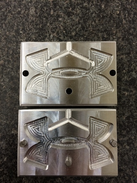
NOTE 2: Keep it shallow (.125 thick or so). Thick parts do not mold well.
NOTE 3: Properly DOCUMENT all operations. Include a print of the tool path for each operation. Must show where origin is.
NOTE 4: Post operations as separate programs. HEADERS Must include an indication of the nature of the operation as well as the tool required (SIZE, FLUTES, MIN STICKOUT).
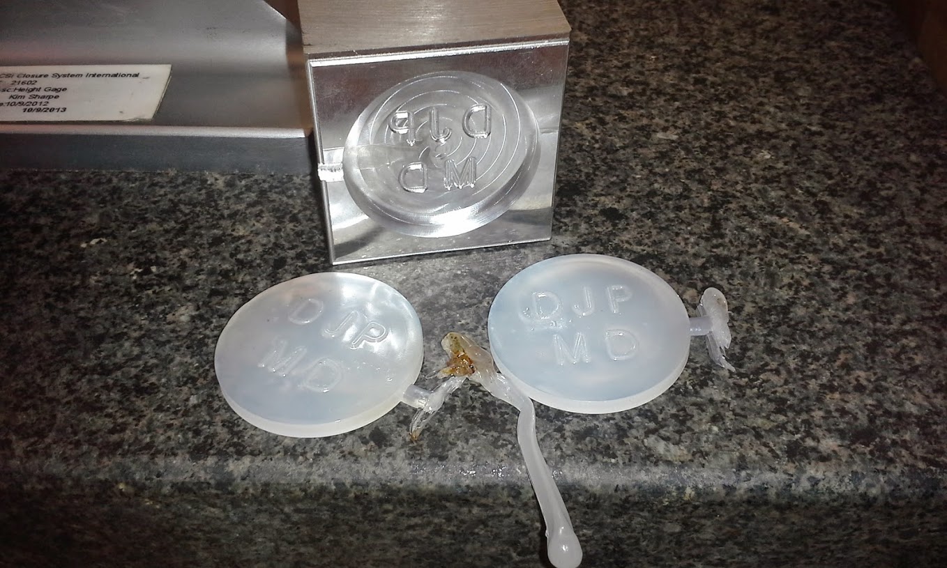
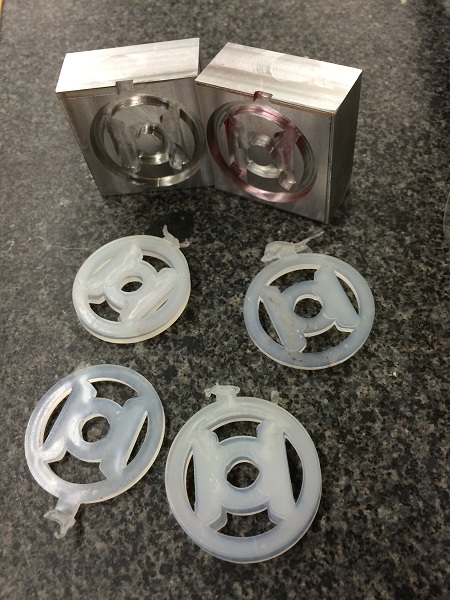
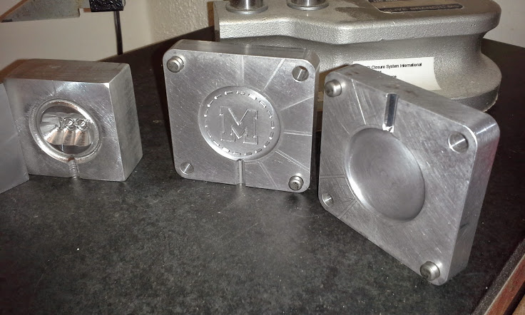
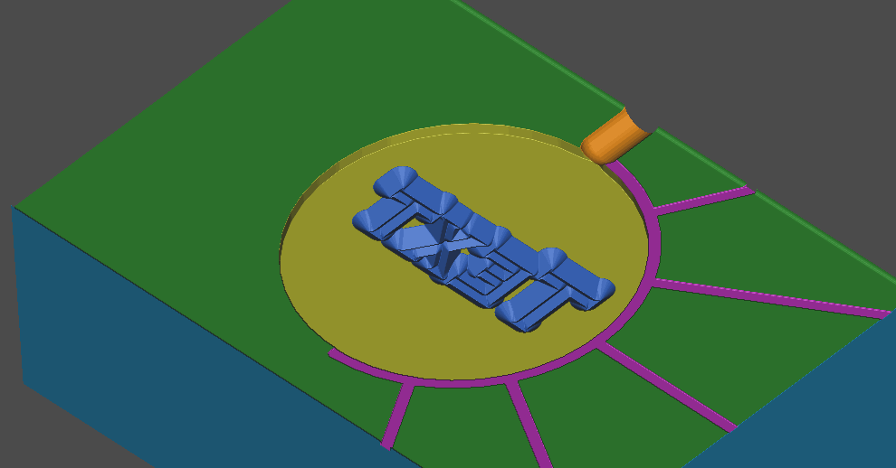
NOTE 5: You must locate the sprue as shown in the examples. Use the ball end mill to cut the sprue. It must be about .090 deep, but can include a gate.
(DRAFT – See New NX12 Manufacturing Basics)
Setup
- Use this model of the Kurt D688 Vise
- Use this model of the SETUP_PARALLELS_1.375
- Origin is upper-left corner of vise (operator’s view)
- DO NOT Use
this model of the vise base (provided)
- DO NOT Use
this model of the 1.625 parallels
Blank Dimensions
- Blank is 1.00 x 2.00 x [4.00 max long]
- 6061 T6 aluminum
Tools available (ONLY USE THESE)
Click for larger view:
Method
Setup
Create assembly, start manufacturing application, create work & part geometry.
Face Milling
- Use 2.0 face mill
- Use Face Milling with Boundaries operation
- NX12 Face Milling Example
- NX12 Face Milling Example 2
Cavity Milling
- Use Cavity Milling operation to cut out main shapes
- Pay attention to the cut levels
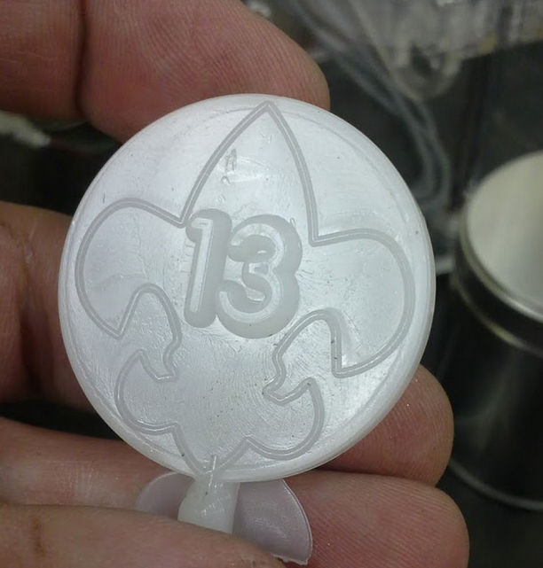
Engraving
Note: You can insert text using “Insert -> Curve -> Text.” I like to use planar text. You can import geometry from AutoCAD if you like.
Version 12: Use Fixed Contour with drive method of Curve/Point. Select a path and press scroll wheel. See this video. Each curve needs to be its own Drive Set. Each drive set will have an engage and retract. These should be set to plunge type (under non cutting moves).
Set part stock (under cutting parameters) to -0.020 or whatever depth you want.
Note: The curve must be not extend beyond the area you want to cut.
Note: Version 12 makes the instruction below obsolete. Use for older versions.
- Use a 90 degree engraving tool
- Use Planar Profile operation
- The part Boundary Geometry mode should be the curve
- When selecting text, it is a good idea to select letter curve loops one at a time, use “Create Next Boundary” (on Create Boundary dialog box) to add each additional letter curve.
- Set tool position to “on”
- Select the curve
- The Floor is the level where the path will be.
- You now need to adjust the non cutting moves to plunge engage /retract instead of leading in/out with arcs.
- Under path settings
- Non Cutting Moves
- Engage: Closed area
- Engage type “plunge”
- Engage: Open Area
- Same as closed area
- Retract: Retract
- Same as Engage
- Be sure engraving tool does not cut away edges of mold.
Deburring
- Use standard workpiece as geometry (blank with workpiece inside)
- Use 90 deg brazed carbide router bit
- Use Planar Profile operation
- Specify part boundaries
- Type is Curve/Edges
- Open type
- Plane automatic
- Material side is left
- Tool position is tanto
- Part Stock is negative amount (on path settings panel, cutting parameters dialog box).
Drilling
- Use Drilling operation
- Be careful to retract above all check geometry
- Setting peck cycle depth
- Click on cycle type (even if it is already peck drill…)
- Ignore “distance, ” click ok
- Number of Steps is “1” click ok
- Now click “increment-none”
- Click “constant” enter increment (.50)
Reaming
- Use a Drilling or Reaming operation, be sure not to peck.
About Rest Milling (Using IPW)
If you need to do several operations in a row that sequentially develop geometry (like roughing, then finishing), you may need to restrict your cutting to the IPW (in process workpiece).
Here is how to do this:
- On the Edit Operation dialog box, go to Path Settings
- Click Cutting Parameters then the Containment tab
- Chang the In Process Workpiece to “Use Level Based“
Note: Possible to extract IPW geometry. Do this in toolpath verify.
Documentation
Be able to demonstrate each of the following at the machine:
- Tool number
- Tool offset (H)
- Origin (e.g., G54)
- Orientation of CSYS (XM, YM, ZM)
- How will tool approach/depart
- Spindle speed
- Feedrate
- Tool minimum stick-out