LECTURE PRESENTATION (old version)
Unit Lectures:
- General Dimensioning Rules
- Advantages of GD&T
- Overview of straighntess (video)
- What is a Feature of Size
- Rule No. 1
- The Feature Control Frame
- Datums
- Types of Tolerances
- Tolerance Zone Modifiers
- The Bonus Tolerance
- Actual Local Size & Actual Mating Envelope
- POSTER
TJ Cyders Links (Ohio University)
Introduction to GD&T
What is it for?
ASME Y14.5 – Dimensioning and Tolerancing
ISO Series of Standards (ISO 129-1:2004)
GD&T advantages
GD&T does (should) not add cost, it is merely a way of being very specific about what you want.
Circular tolerance zones result in greater accuracy with “looser” tolerances
Improved, more specific, more universal communication of ideas.
Simplified, systematic inspection procedures.
General Dimensioning Requirements
Fundamental Rules (Sec. 1.4)
- Each dimension shall have a tolerance, except for those dimensions specifically identified as reference, maximum, minimum, or stock (commercial stock size)
- Dimensioning and tolerancing shall be complete so there is full understanding of the characteristics of each feature.
- Each necessary dimension of an end product shall be shown. No more dimensions than those necessary for complete definition shall be given. The use of reference dimensions should be minimized.
- Dimensions shall be selected and arranged to suit the function and mating relationship of a part and shall not be subject to more than one interpretation.
- The drawing should define a part without specifying manufacturing methods.
- It is permissible to identify as nonmandatory certain processing dimensions that provide for finish allowance, shrink allowance, and other requirements, provided teh final dimensions are given on the drawing. Nonmandatory processing dimensions shall be identified by an appropriate note, such as NONMANDATORY (MFG DATA).
- Dimensions should be arranged to provide required information for optimum readability. Dimensions should be shown in true profile views and refer to visible outlines.
- Wires, cables, sheets rods, and other materials manufactured to gage or code numbers shall be specified by linear dimensions indicating the diameter or thickness. Gage or code numbers may be shown in parentheses following the dimension.
- A 90degree angle applies where center lines and lines depicting features are shown on a drawing at right angles and no angle is specified.
- A 90degree basic angle applies where center lines of features in a pattern or surfaces shown at right angles on the drawing are located or defined by basic dimensions and no other angle is specified.
- Unless otherwise specified, all dimensions are applicable at 20 degrees C (68 F).
- All dimensions and tolerances apply in a free state condition.
- Unless otherwise specified, all geometric tolerances apply for ful depth, length, and width of the feature.
- Dimensions and tolerances apply only at the drawing level where they specified. A dimension specified for a given feature on one level of drawing, for example, a detail drawing) is not mandatory for that feature at any other level (for example, an assemly drawing).
Units of Measurement
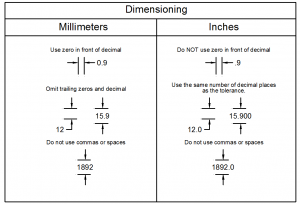
Be sure to indicate on the print a note such as: UNLESS OTHERWISE SPECIFIED, ALL DIMENSIONS ARE IN MILLIMETERS (or INCHES).
Millimeter Dimension
- Zero precedes the decimal point.
- If the dimension is a whole number, do not include a decimal point or trailing zero.
- Do not include trailing decimal zeros.
- Do not use commas or spaces to group digits.
Decimal Inch Dimensioning
- Do not precede dimension with a zero.
- A dimension is expressed to the same number of decimal places as its tolerance. Use trailing zeros as necessary.
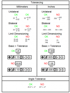
Assigning a Geometric Tolerance
Feature Control Frame
- Geometric Characteristic Symbol
- Tolerance Zone Descriptor
- Geometric Tolerance (TIM/TIR)
- Material Condition Symbol
- Primary Datum
- Secondary Datum
- Tertiary Datum
- Material Condition Symbol for Datum
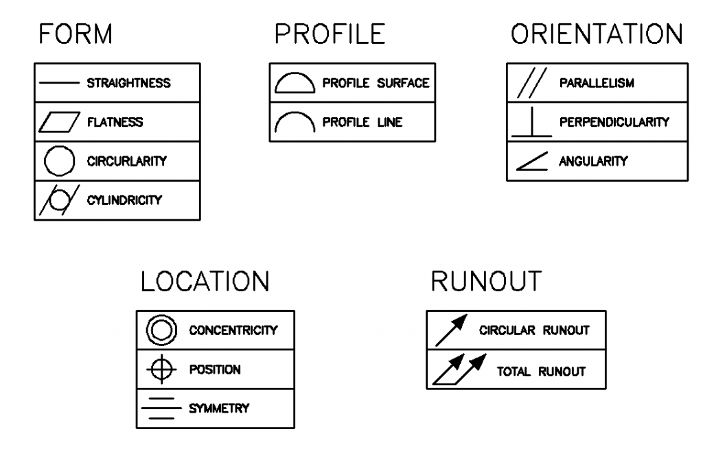
Types of Geometric Tolerances
- Form
- Straightnes
- Flatness
- Circularity
- Cylindricity
- Profile
- Profile of a Surface
- Profile of a Line
- Orientation
- Parallelism
- Perpendicularity
- Angularity
- Runout
- Circular Runout
- Total Runout
- Location
- Concentricity
- Position
- Symmetry
Rule #1
Where only a tolerance of size is specified, the limits of size of an individual feature prescribe the extent to which variations in its geometric form, as well as size, are allowed.
Datums
GD&T Bibliography
Some links may require UM campus network connection.
http://machinedesign.com/article/new-asme-y145-2009-standards-for-gdt-1020
Branch, Ron. “The Changing Face Of Part Inspection.” Machine Design 82.18 (2010): 54-56. Applied Science & Technology Full Text (H.W. Wilson). Web. 2 Oct. 2012. <link>.
Clark, Richard. “Bonus Tolerances For GD&T.” Tooling & Production 71.2 (2005): 28-29. Applied Science & Technology Full Text (H.W. Wilson). Web. 2 Oct. 2012. <link>.
Day, Don. “Defining GD&T.” Quality 46.4 (2007): 18-21. Applied Science & Technology Full Text (H.W. Wilson). Web. 2 Oct. 2012. <link>.
Krulikowski, Alex, and James R. Roll. “GD&T – Early Warning For Bad Designs.” Machine Design 81.5 (2009): 50-58. Applied Science & Technology Full Text (H.W. Wilson). Web. 2 Oct. 2012. <link>.
Hetland, Greg1, greg-hetland@iigdt.com, and Dan2, daniel.goldman@honeywell.com Goldman. “ACHIEVE HIGHER MECHANICAL PRECISION WITH Profile Tolerancing.” Quality 50.12 (2011): 34-36. Applied Science & Technology Full Text (H.W. Wilson). Web. 2 Oct. 2012.<link>.
Krulikowski, Alex. “Nine Myths About Geometric Dimensioning And Tolerancing.” Quality 42.10 (2003): 21-22. Applied Science & Technology Full Text (H.W. Wilson). Web. 2 Oct. 2012.<link>.
Lin, Cheng Y.1, and Nathan J.2 Luetke. “Calculation Of Tolerance Stacks Using Direct-Position Approach In Geometric Dimensioning And Tolerancing.” Journal Of Engineering Technology 28.1 (2011): 10-15. Applied Science & Technology Full Text (H.W. Wilson). Web. 2 Oct. 2012.<link>.
Sabo, John. “Dimensions And Tolerancing—It Can Make Your Life Easier.” Electronic Engineering 73.890 (2001): 109-110. Applied Science & Technology Full Text (H.W. Wilson). Web. 2 Oct. 2012.<link>.
Tandler, Bill, GDandTWorkshop@qualitymag.com. “The Perfect Imaginary World Of Gd&T.” Quality 51.2 (2012): 22-23. Applied Science & Technology Full Text (H.W. Wilson). Web. 2 Oct. 2012.<link>.
Tandler, Bill. “The Imperfect Real World Of Physical Parts.” Quality 51.3 (2012): 20-22. Applied Science & Technology Full Text (H.W. Wilson). Web. 2 Oct. 2012. <link>.


