REVISED 8-27 at 8:35 pm
The Eventorbot is an open source 3D printer developed by Duy Dang. The steel tube frame makes this printer design simple and strong. Eventorbot designs, assembly tutorials and bills of materials are freely available online. The plans are licensed CC-BY-SA.
For this assignment, you will do the following:
- Reverse engineer the STL files to create fully parametric models of the “printed” parts.
- Find a source for each purchased part. Acquire STEP models of purchased parts. IGES can substitue for step.
- If you cannot find STEP or IGES files, model the purchased parts.
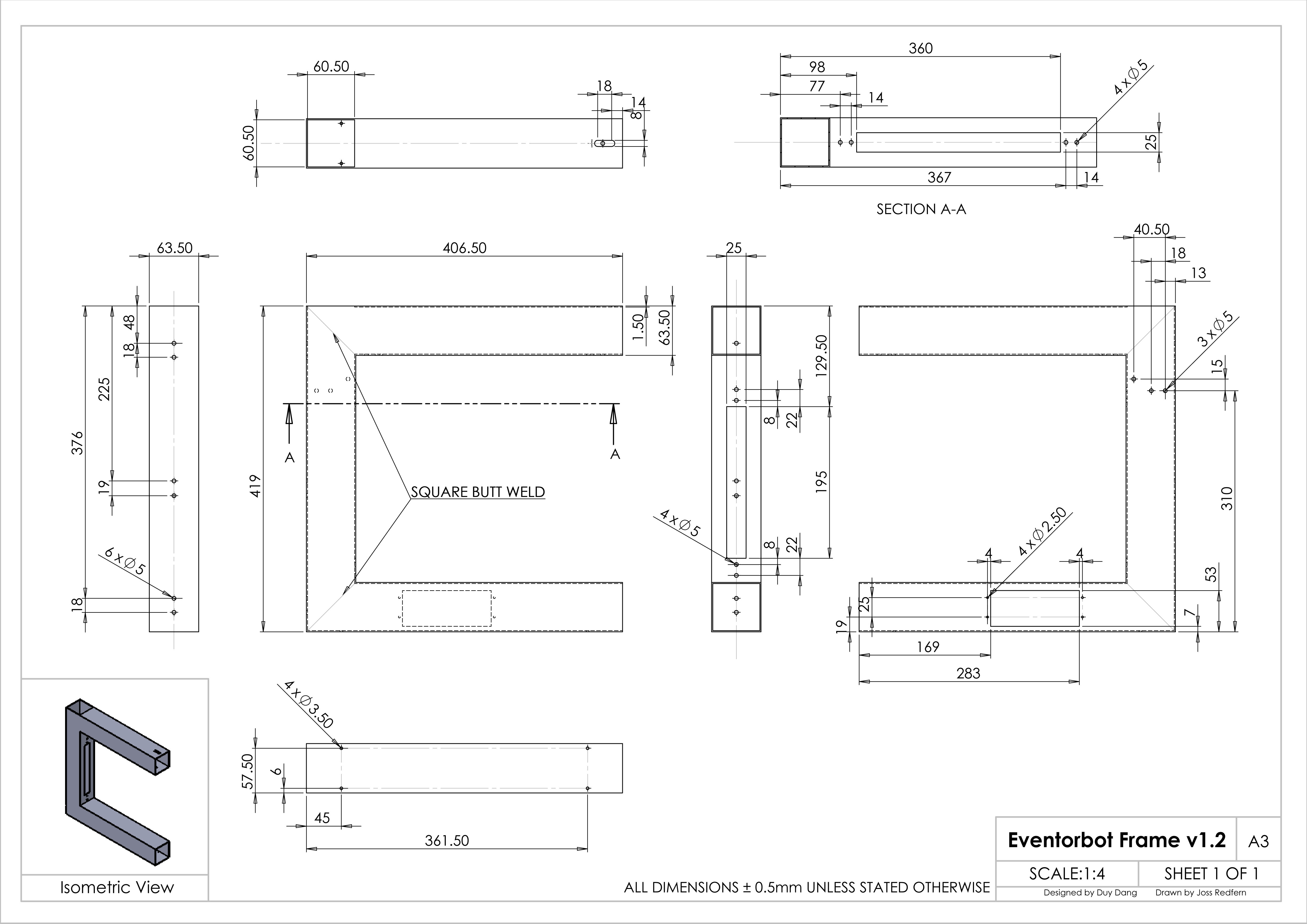
- Create Parametric models of the frame (drawing here).
- Create Parametric models of any purchased parts that must be modified (e.g., rod cut to length).
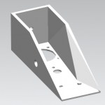
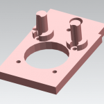
- Create a sheet metal component of the print head holder.
- Create an assembly of all components.
- Create a rendered view of the sub-assemblies and the completed assembly.
- Create exploded views to illustrate assembly process (example).
- Create a document explaining the device and how each sub-system works and goes together. Summarize sources for the entire BOM (including part numbers, costs). Include a section that details each team member’s contribution. You may consider creating and assembly that is color-coded by student. Turn in as a PDF or Word Document.
Heater Heads (Use Mark V Head assembly)
Version 1.0 Hardware
- (1) 4′ long, 2 1/2″ metal square tube (Diagram)
- (3) Nema 17 stepper motor (at least 3 kg-cm 4 Wire) Specs for current motors used
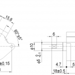
- (1) Geared stepper motor for extruder. (model: PG35L-048) Datasheet
- (12) 8mm linear bearings, model: LM8UU. Pic
- (4) 8mm ball bearing, model: 608Z. Pic
- (1) 9 1/2″ long 5/16 threaded rod (for Z axis). Note: Most likely you will have some leftover after your 9 1/2″ cut, use that piece to cut a 13mm long piece for this
- (6) 10.5″ long 8mm rod. Pic
- (1) Coupler 5mm to 8mm. Pic
- (1) Set of printed plastic parts (stl files listed on thingiverse.com)
- (optional) 1 set of printed decorative end caps (stl files listed on thingiverse.com)
- (1) Set of screws. List
- (1) Sanguinololu 1.3a mother board with ramps. Ramps to be compatible to steppers. Pic
- (1) MK7 drive gear (gear to drive the filament)Pic
- (1) 4 ft of XL timing belt (source, pick style. Does not have to be modeled). PDF
- (4) Push button momentary end stop switches. Pic
- (1) Bed. Aluminum or pexi-glass 8.5″ x 11″, ~1/8″ thick Diagram
- (4) Springs for bed
- (8) Rubber feet (bore holes need to be able to allow 10-32 screws) Pic
- (1) Roll of 1/4″ black poly tubing. Cut to: (1)14″ for hothead wires, (1)20″ for filament feeder, (1)12″ for bed to mother board tray connection Pic
- (6) Air pneumatic tube 6mm push in connector fittings. (Total Size 21mm x 12mm/ 0.82″ x 0.47″(L*W) Thread Diameter 9mm/ 0.354) Pic
- (1) 5.5 mm x 2.1mm DC power jack socket female panel mount connector Pic
- (1) Laptop charger 12 volt DC at least 5 amp (13 amp is using hotbed) Pic
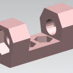
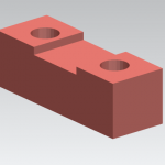
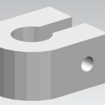
Printable plastic parts (STL Files, with converted to “dumb” PRT files)
Note: Several of these files contain errors. Part of your job is to find and fix these errors and inconsistencies.
- (2) bed A p1 P-022 NX: bed A p1 P-022
- (2) bed A p2 P-023 NX: bed A p2 P-023
- (1) bed p1 P-020 NX: bed p1 P-020
- (1) bed p2 P-021 NX: bed p2 P-021
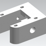
- (2) footing 1 P-009 NX: footing_1_P-009
- (4) footing 2 P-010 NX: footing_2_P-010
- (3) motor mount P-005 NX: motor_mount_P-005
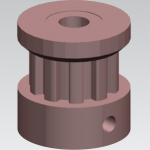
- (2) pulley gear P-006 NX: pulley_gear_P-006
- (2) * rod support p2 P-017 NX: rod_support_p2_P-017
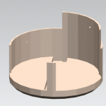
- (1) spool holder P-011 NX: spool_holder_P-011
- (1) * spool holder 2 P-011 NX: spool_holder_2_P-011
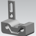
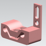
- (1)* X carriage P-007 NX: x_carriage_P-007
- (1)* Z carriage p1 P-018 NX: z_carriage_P1-018
- (1)* z carriage p2 P-019 NX: z_carriage_p2_P-019
Optional Decorative caps
- (2) corner cap P-001 NX: corner_cap_P-001
- (2)* end cap P-004 NX: end_cap_P-004
*Physical model available
Zip File of all STEP models: Step Files