There are two Haas TM1 Mills in ET112.
Machine A
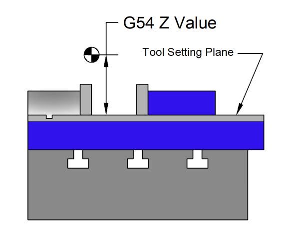
Is the newer TM1 with the enclosure. Tools for this machine are set with reference to the top plane of the vise base as shown below. The G54 Z offset is equal to the distance to the program zero from this plane.
The vise model is available here: Kurt D688 Vise
The XY origin for G54 is typically set as shown below. Default values for this are typically posted on the machine enclosure.
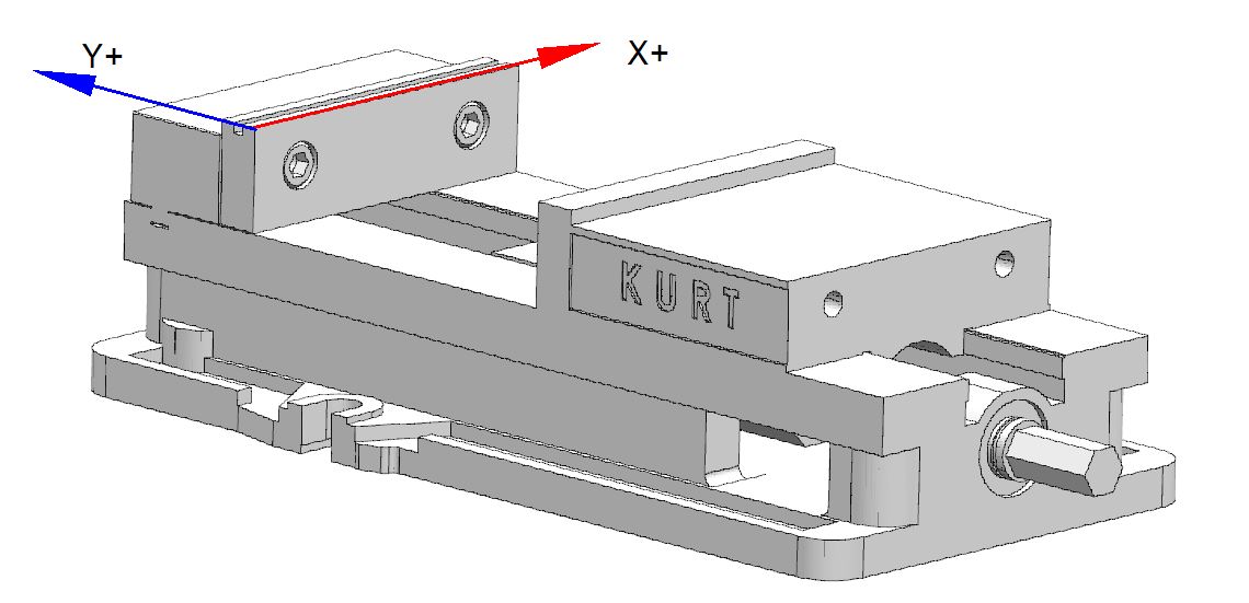
If you are in doubt, ask your instructor.
The parallel models are available here:
- SETUP_PARALLELS_0.750
- SETUP_PARALLELS_0.875
- SETUP_PARALLELS_1.000
- SETUP_PARALLELS_1.125
- SETUP_PARALLELS_1.250
- SETUP_PARALLELS_1.375
- SETUP_PARALLELS_1.500
- SETUP_PARALLELS_1.625
- SETUP_PARALLELS_1.750
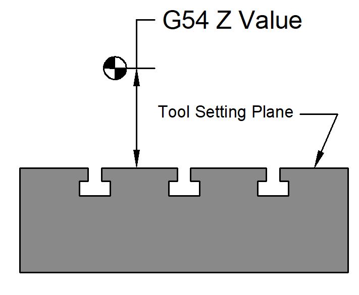
Machine B
Is the older TM1. Tools for this machine are set with reference to the machine table (with the T-slots). The G54 Z offset is equal to the distance to the program zero from this plane.
X and Y origins for G54 on this machine are set on an ad-hoc basis. There is no default position unless noted on the machine itself.
Tool Offset Setting Sequence (for machines in ET112)
☐ Be sure the tool setter is calibrated to a 2.0000 height.
☐ Position the tool setter on the tool setting plane (See illustrations above).
☐ Enter HAND JOG mode.
☐ Load the desired tool into the spindle
☐ Jog the tool down until the tool setter reads “zero.” Be CAREFUL!
☐ Go to the tool offset screen.
☐ Highlight the line number of the tool you are setting.
☐ Press TOOL OFFSET MEASURE.
☐ Type -2.0 and press WRITE/ENTER. This will subtract two inches from the length offset.
This is to account for the two-inch height of the tool setter.
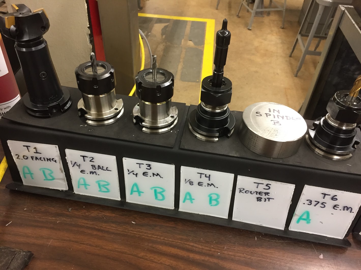
Keeping track
Remember: Using the wrong tool will cause a crash.
Each tool has an acrylic placard with the tool number and the diameter. When the tool has been set in Machine A, this letter will be written on the placard with dry erase marker. If the tool offset becomes invalid, the letter is erased.
Default tool numbers and machining parameters are kept on the Tool Number worksheet.