Notes
Material
6061-T6511 aluminum flat bar 1.25 wide, .25 thick
Model
Working Drawings
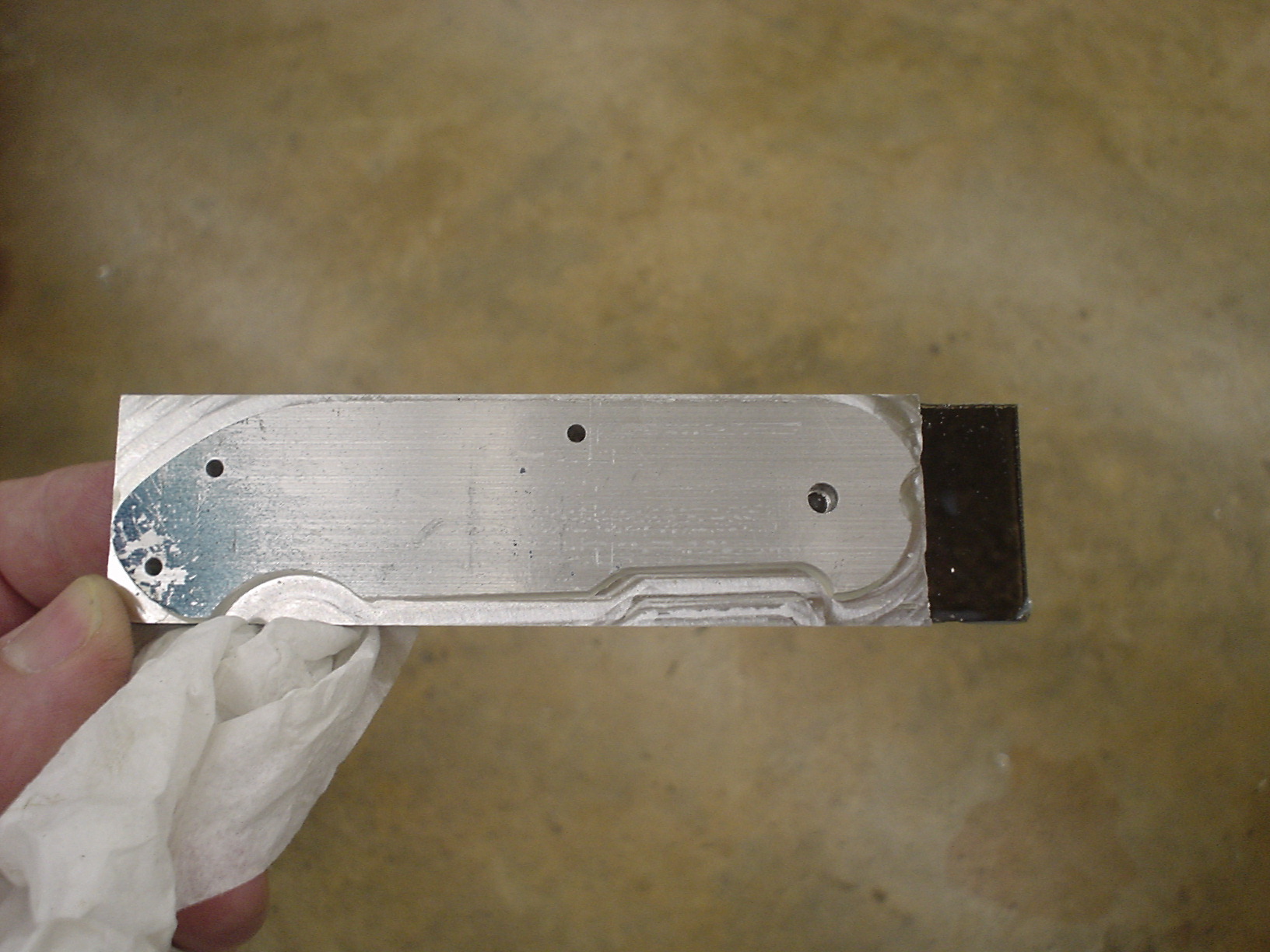
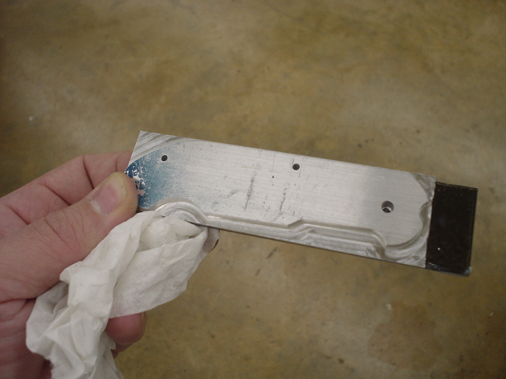
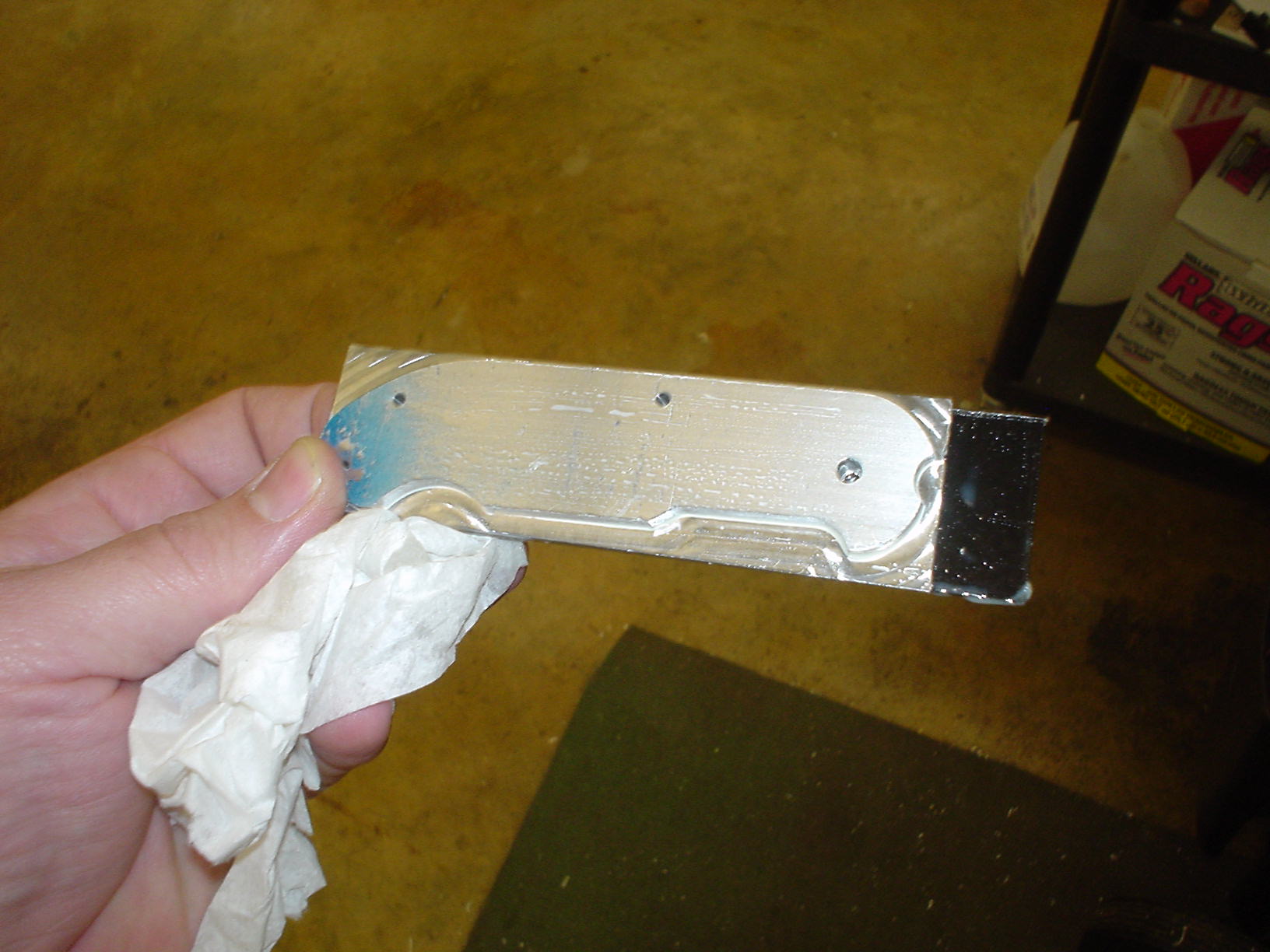
Part
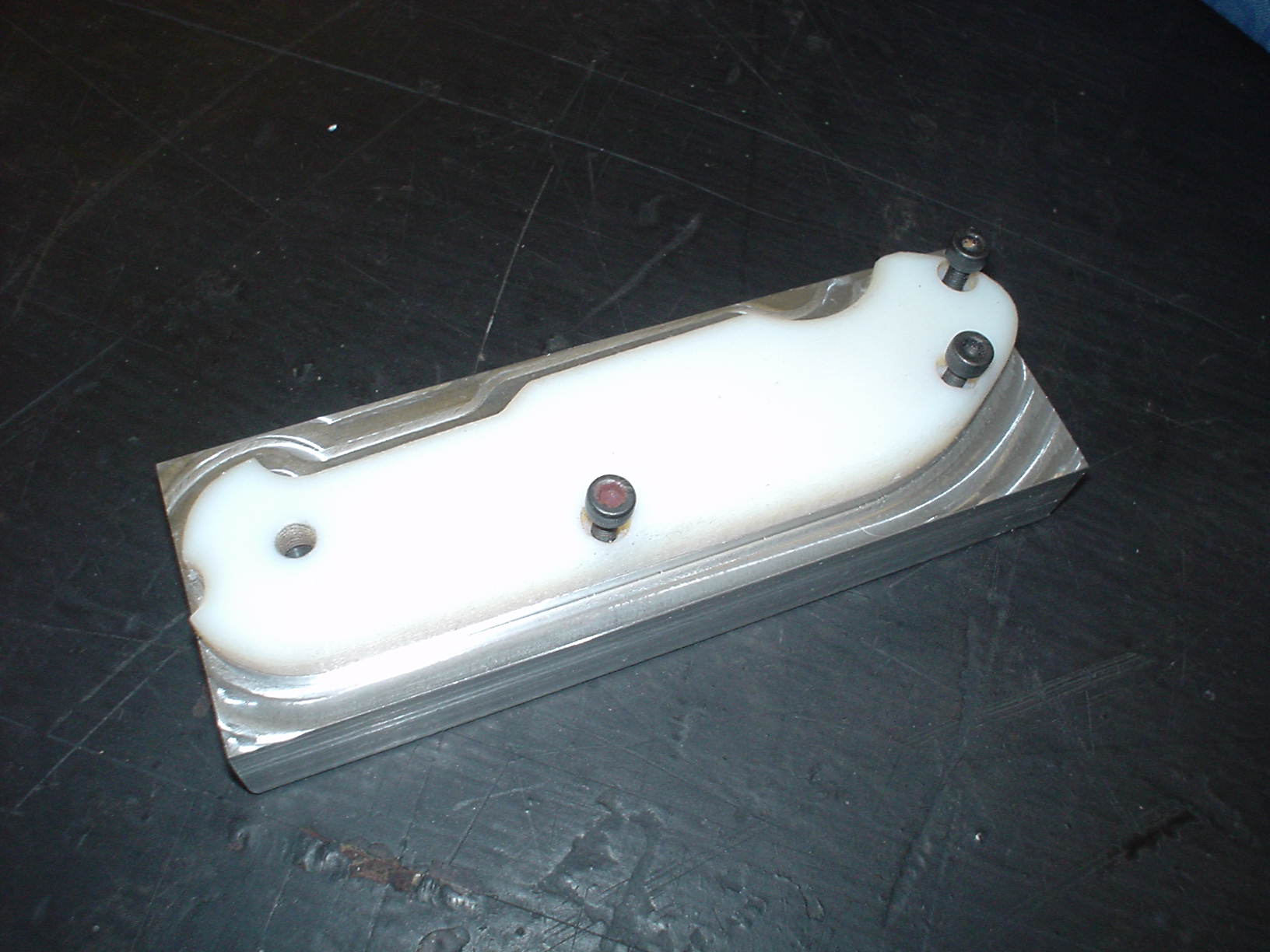
Fixture
Process Routing
Position A
- Shear to length (CTS Ironworker)
- Assemble on “special parallel” (Haas TM1)
- Internal inside vise, machined side toward fixed jaw
- Slide to locating pin
Position B
- Assemble on 003 FXT
- Standard Vise position
- Slide to locating pin
Position C
- Assemble UPSIDE DOWN on 002 FXT (Opposite side fixture)
- Standard Vise position
- Slide to locating pin
Draft 5S Layout
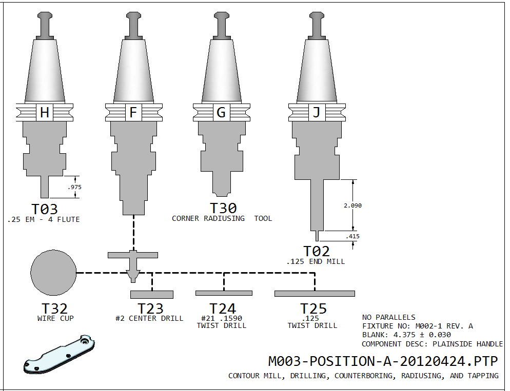
Tool Numbers (ref. only) Refer to master list for current details.
For Position A
- T03 (Holder H) 4fl end mill .250 diameter
- T23 (Holder F) #2 Center Drill
- T21 (Holder F) .1935 jobber twist drill
- T25 (Holder F) .125 jobber twist drill
- T02 (Holder J) .125 4fl end mill
- T30 (Holder G) Interstate corner radius tool
For Position B
- T03 (Holder H) 4fl end mill .250 diameter
For Position C
- T02 (Holder J) .125 4fl end mill

CAM Files
CNC Files
Setup 1
1.625 parallels, .090 Spacer

Setup 2
1.5 parallels, .003 fixture

Setup 3
Flip over onto 002 fixture

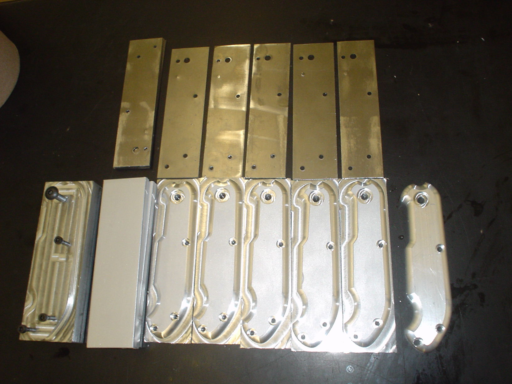
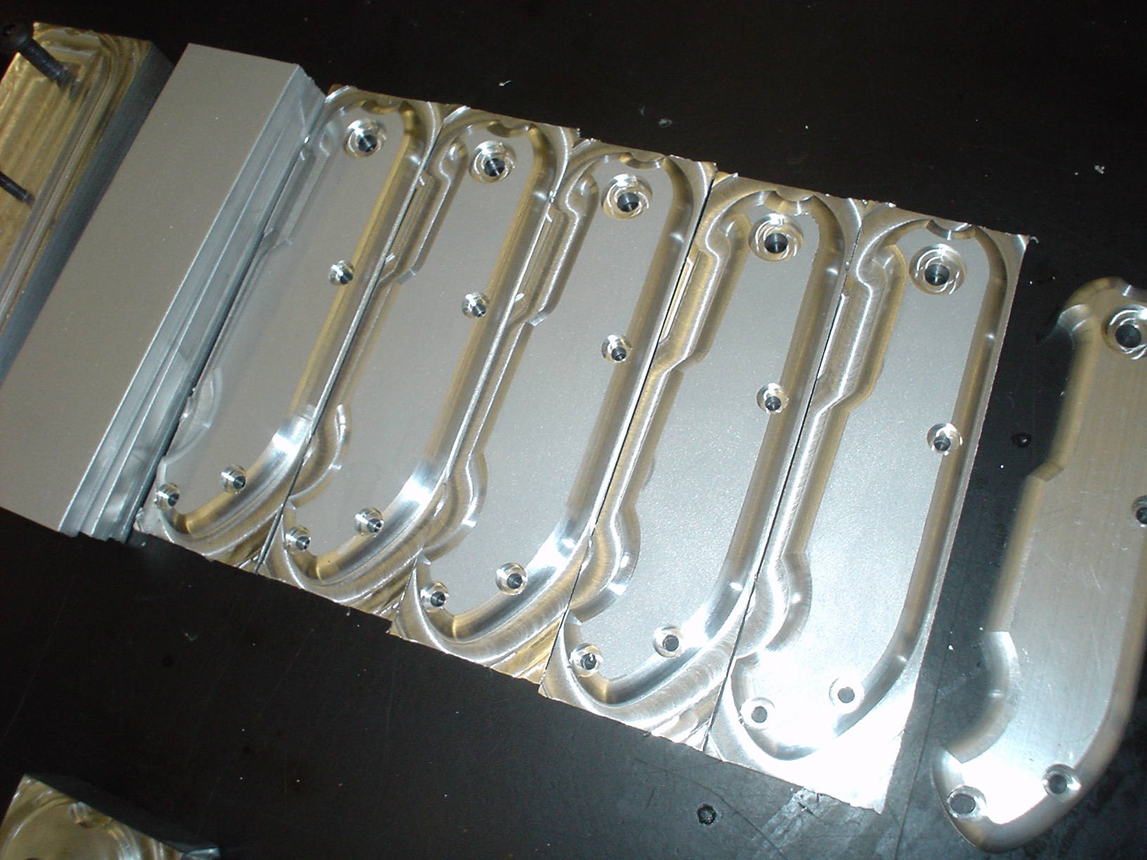
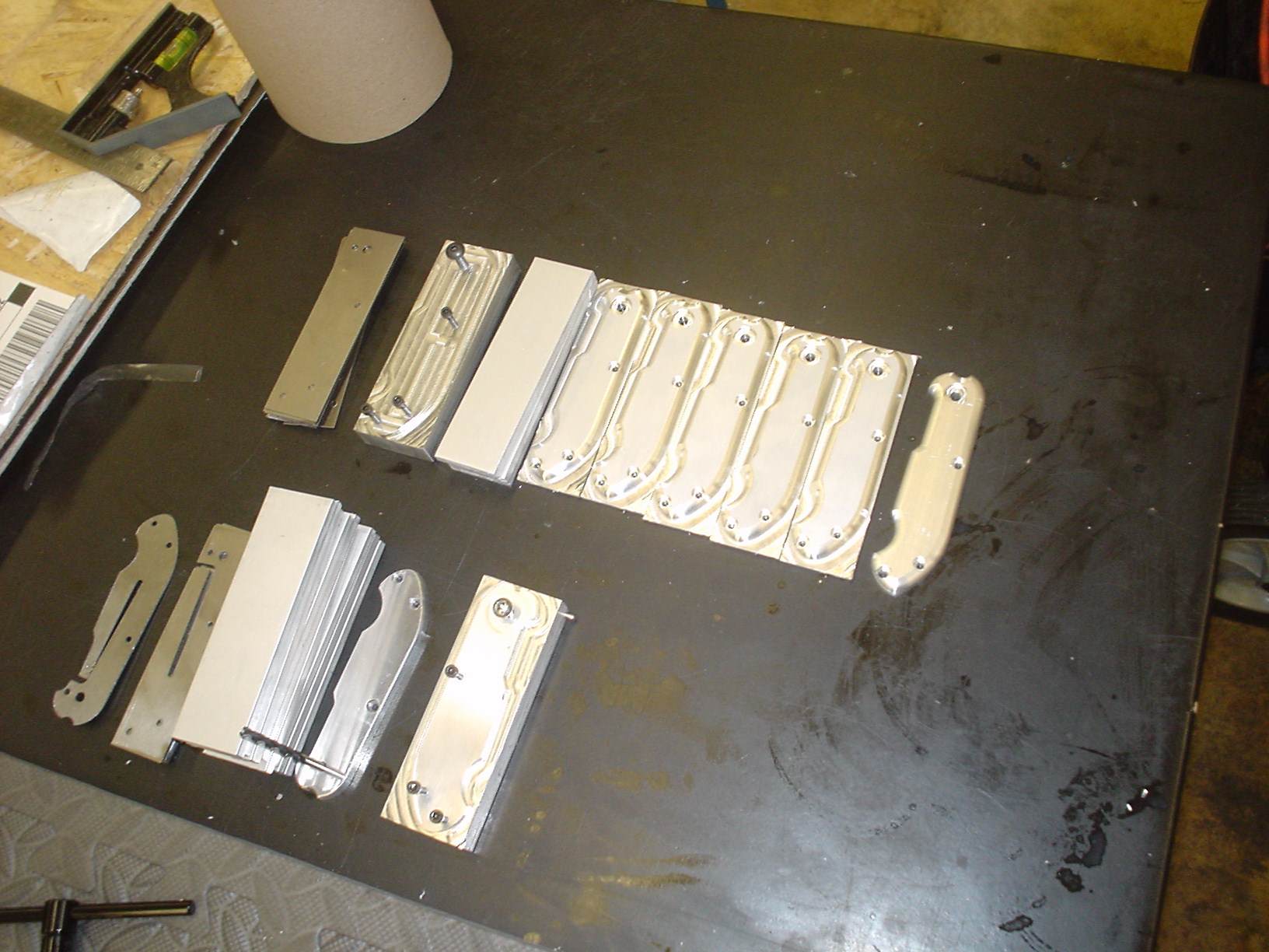
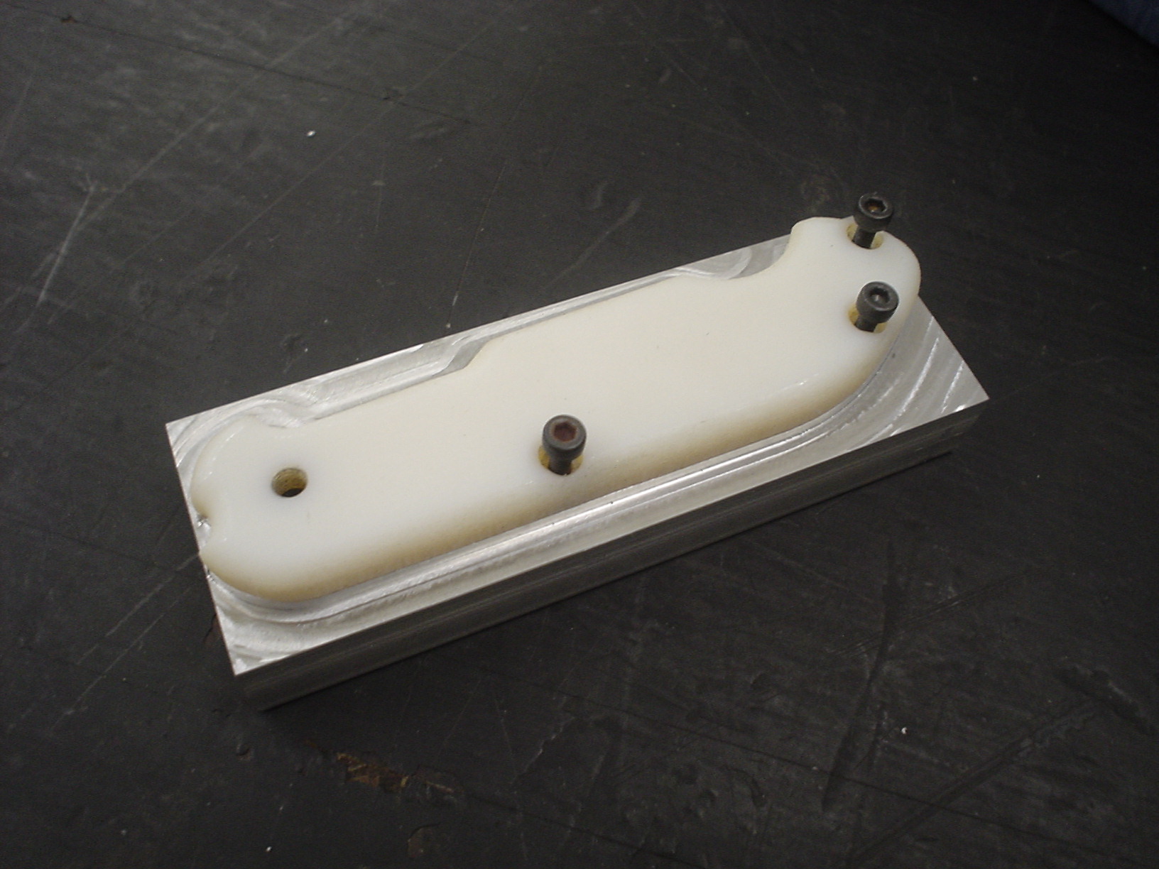
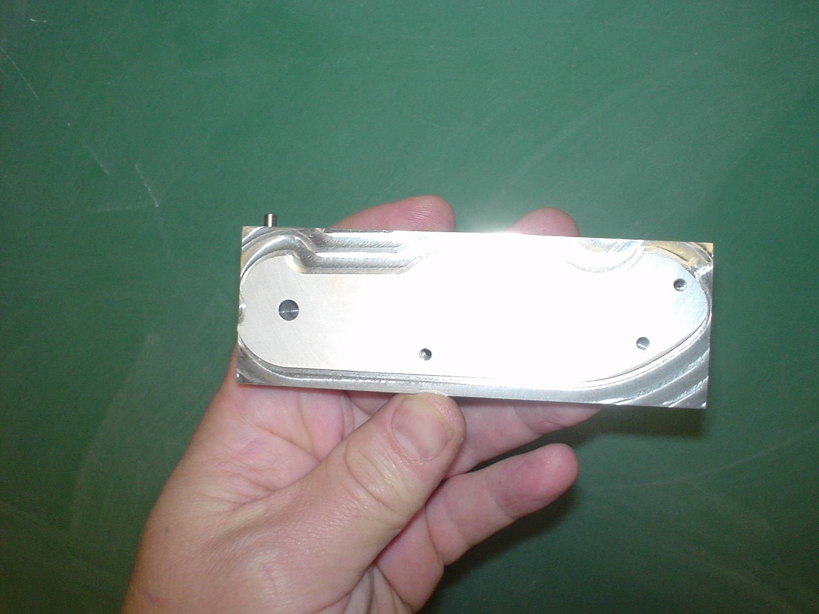
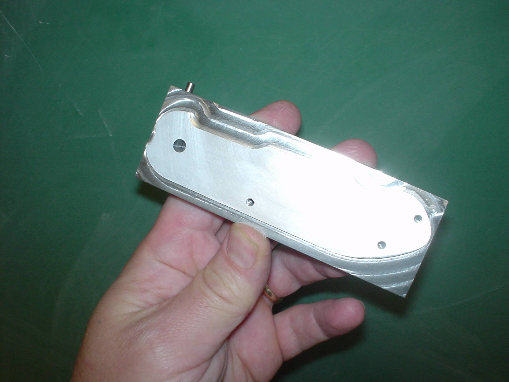
003_CNC_C1_drillStop – PLAIN HOLE LEFT
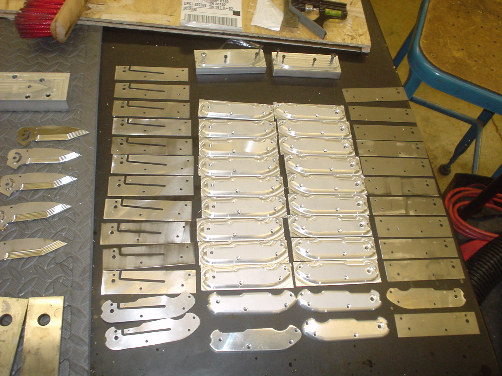
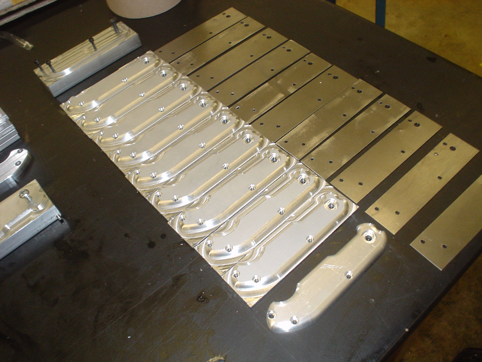
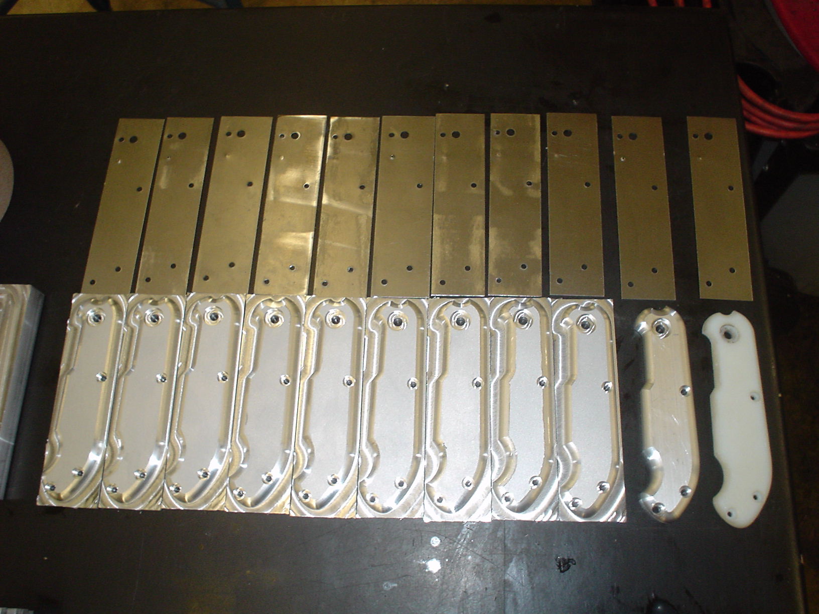
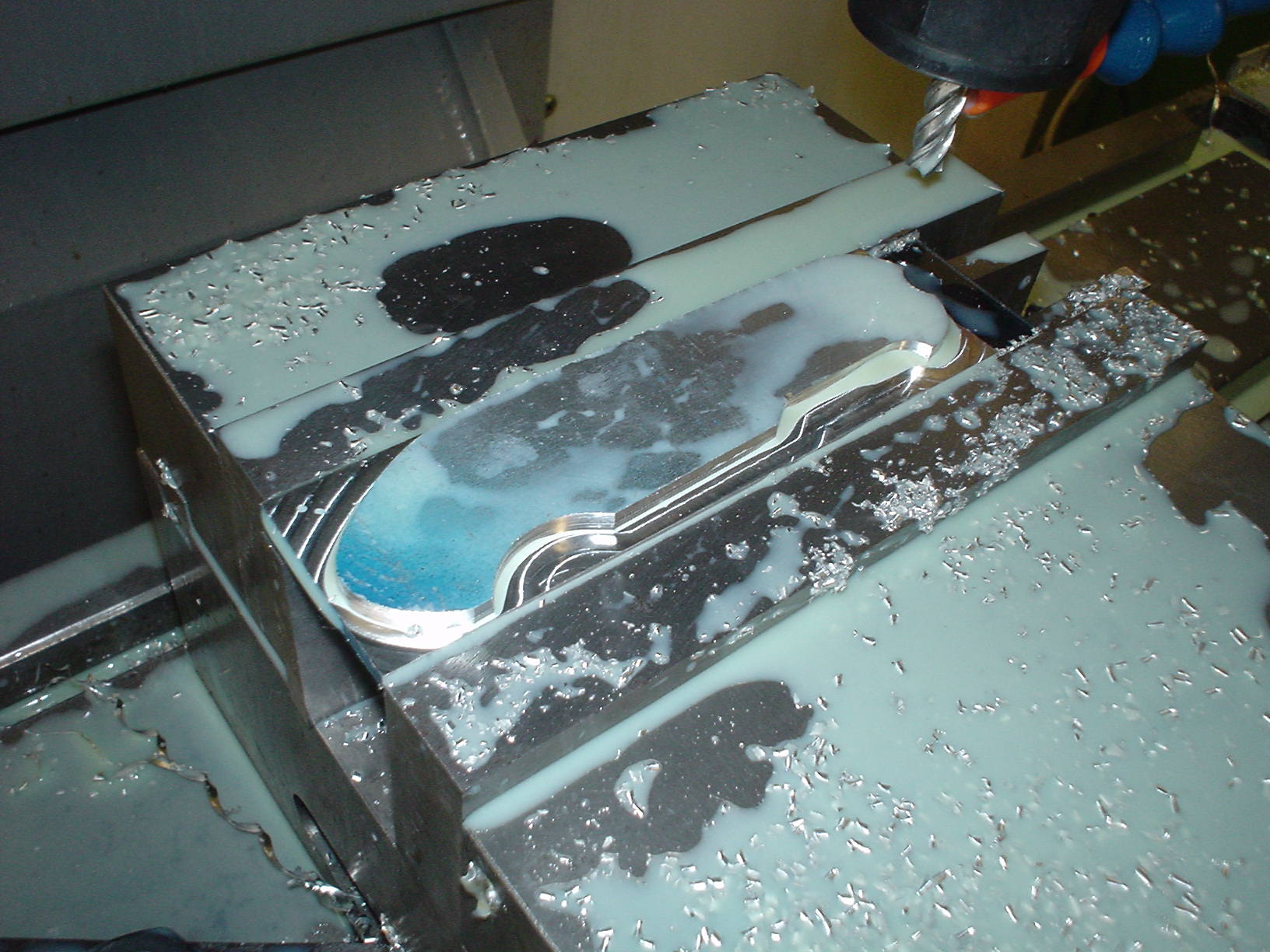
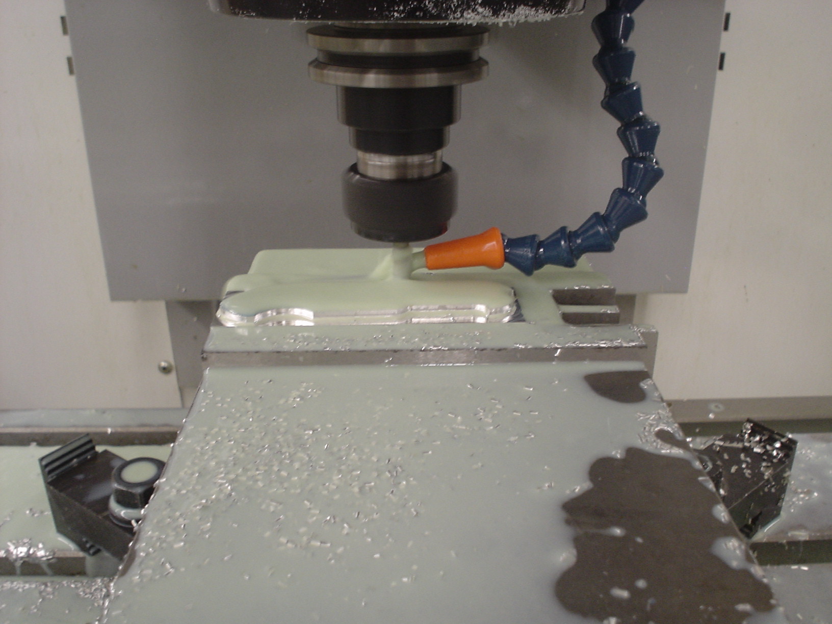
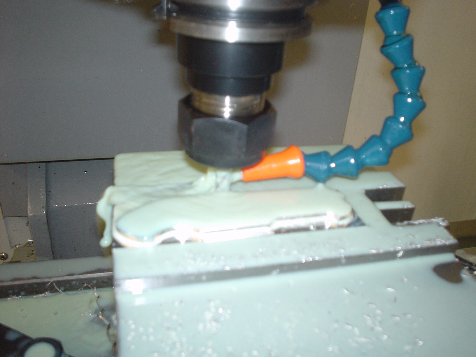
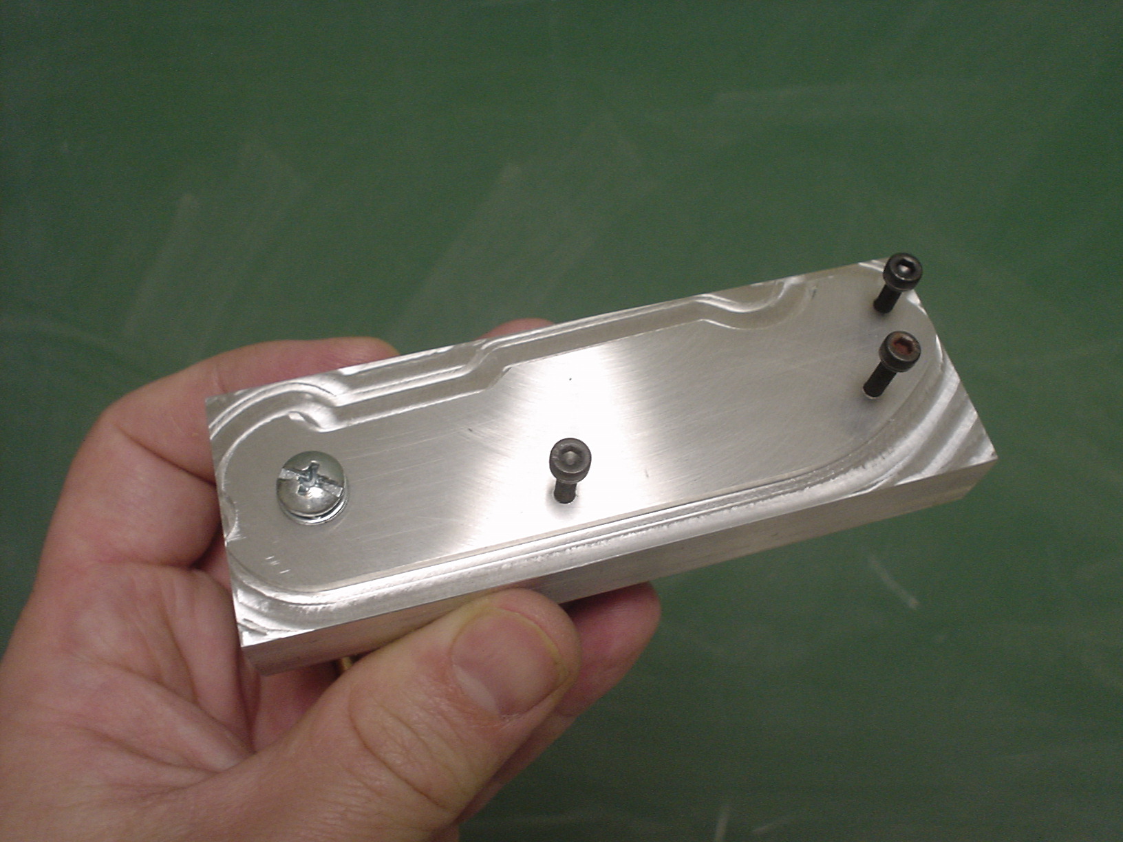
Photos