A Typical CNC Control Panel
Power On/Off
Emergency Stop (E-Stop)
Reset
Cycle Start
Typical Machine Modes
- MDI (manual Data Input)
- Memory
- Edit
- Jog
- DNC
Jog Handle
Load Meter
Keypad
Speed and Feed overrides
Settings and Machine Parameters
Coordinate System Offsets
Tool Length Offsets
Before a program can be run, there needs to be complete agreement between the machine and the programmer about the geometry of the program. This includes agreement of the coordinate system origin, the length of the tools and the location and size of the workpiece.
A Typical CNC Control Panel
Power On/Off
Many machines have a recommended shutdown sequence when shutting the power down. Be sure to check the manual for the particular machine before powering it down.
Emergency Stop (E-Stop)
 The E-Stop is usually the most noticeable button on the controller. E-Stops generally stop all motion on the machine. Often, a machine will need to be re-zeroed after an E-Stop button has been pressed. They are not used as a way to power down or stop the machine temporarily.
Reset
Reset is used if a non-emergency event stops the machine from operating. An example of this could be a syntax or other error programming error. Reset does not clear modal commands. Modal commands are those that stay set until they are turned off (See p. 10).
Cycle Start
Usually a large green button, the cycle start button starts the execution of the program that is in the memory. You must be certain what the machine is going to do before pressing this button. The machine will not stop to ask you questions after you press this button!
MDI (manual Data Input)
Often, while working with a machine, a programmer will need to execute a few lines of code to make the machine perform some simple function. An example may be to turn the spindle on to warm it up and get it properly lubricated before putting a “cold” machine into service. Usually pressing the MDI button will take the operator to a text input screen and enable the keyboard on the controller. Although it is possible to do so, MDI is not often used to write complete programs because typing on a controller is not very efficient or comfortable.
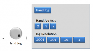
Jog Handle
 With traditional manual machines, axes were moved by turning wheels located at the end of leadscrews. On CNC machines, these axes are turned with motors under the direction of the controller. If a programmer wishes to move a CNC controlled axis, it is necessary to do so through the controller. The jog wheel is used for this purpose. Usually, the controller must be put into a special “HAND JOG” mode via some button or switch. In hand jog mode, the operator selects the axis they want to manipulate, as well as the level of resolution at which they wish to control the motion with.
Load Meter
Most CNC machines are equipped with some kind of meter to measure the forces acting on the spindle and the axes of motion. Some are designed to stop a cycle if a load level reaches a certain threshold. Since there is no tactile feedback as there is in most manual equipment, load meters are a way of monitoring how “hard” a machine is working.
Keypad
Alpha-numeric keypads are provided on most machines as a convenient way to modify existing programs or to write simple programs while at the machine. These are sometimes arranged in a QWERTY keyboard layout or sometimes in alphabetical order.
Speed and Feed overrides
Calculated speeds and feeds are at best an educated guess at what will be the best performing combination for the cutting tool, material, and cutting conditions. Often this needs to be adjusted at the machine in real time as the material is being cut. Override buttons allow the operator to speed up or slow down incrementally the speed and feed of a program. It is a good practice to note any adjust to speeds and feeds of programs during prove-out, and modify the program so that in production the overrides remain at 100%.
There is usually a separate override for rapid travel, such as 5%, 20% and 50% rapid travel.
Offsets Pages
Tool length and diameter offsets
Work Coordinate System offsets
Screen (CRT)
Settings and Machine Parameters
Coordinate System Offsets
Work Offsets Register
Edge finders
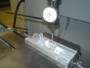
Coaxial Dial Indicator
Setting up a Lathe
Tool Length Offsets
Tool Offsets Register
Tool Probes
Tool Setters and Presetters

