Warmup
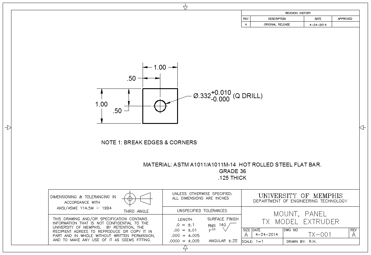
Draw the TX-001 Panel Mount (component only, no dimensions)
Introduction
Accuracy and precision is one of the fundamental advantages of using CAD. You must be absolutely specific about where things like lines begin and end.
You will also learn about layers. Layers are used to keep groups of data separate from each other. For example, you can put entities that represent different components on different layers.
Commands to Know
DAL
DIMANG
DIST
LAYER
LINE
NEW
ORTHO (F8)
OSNAP
SAVE
SAVEAS
UNDO
Variable: OSMODE ( I set mine to 39)
Procedure
Start a new drawing.
Save it as lab2_[Lastname_F].dwg
For example: lab2_hewitt_r.dwg
Create a layer called “Axes,” make it blue.
Create a layer called “Entities,” make it yellow.
Draw a line from -10 , 0 to 10 , 0
Draw a line from 0 , -10 to 0 , 10
Put those two lines on layer “Axes.”
Make the current layer “Entities.”
Draw a line from 4.54 , 2.21 to -2.60 , -1.00 (we will call this “Line A”).
Draw a line from -6.88 , 3.4 to 0 , 0 (we will call this “Line B”).
Using lines, draw a 2.30 x 4.50 rectangle whose lower left corner is at 2.3123, 5.5640. Orient the rectangle so the long side is parallel with the X axis.
Print out the PDF file below and fill in the blanks. This is what you will turn in for this lab.