Notes
Material
6061-T6511
Model
Working Drawings
Part
Fixture
Process Routing
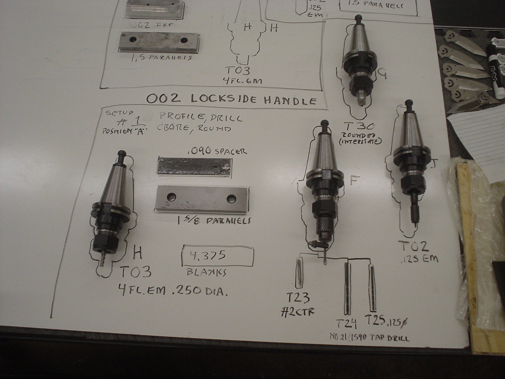
Position A
- Shear to length: 4.40 +/- .050 (CTS Ironworker)
- Assemble on “special parallel” (Haas TM1)
- Internal inside vise, machined side toward fixed jaw
Slide to locating pin

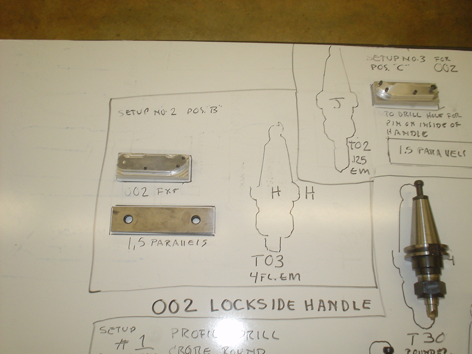
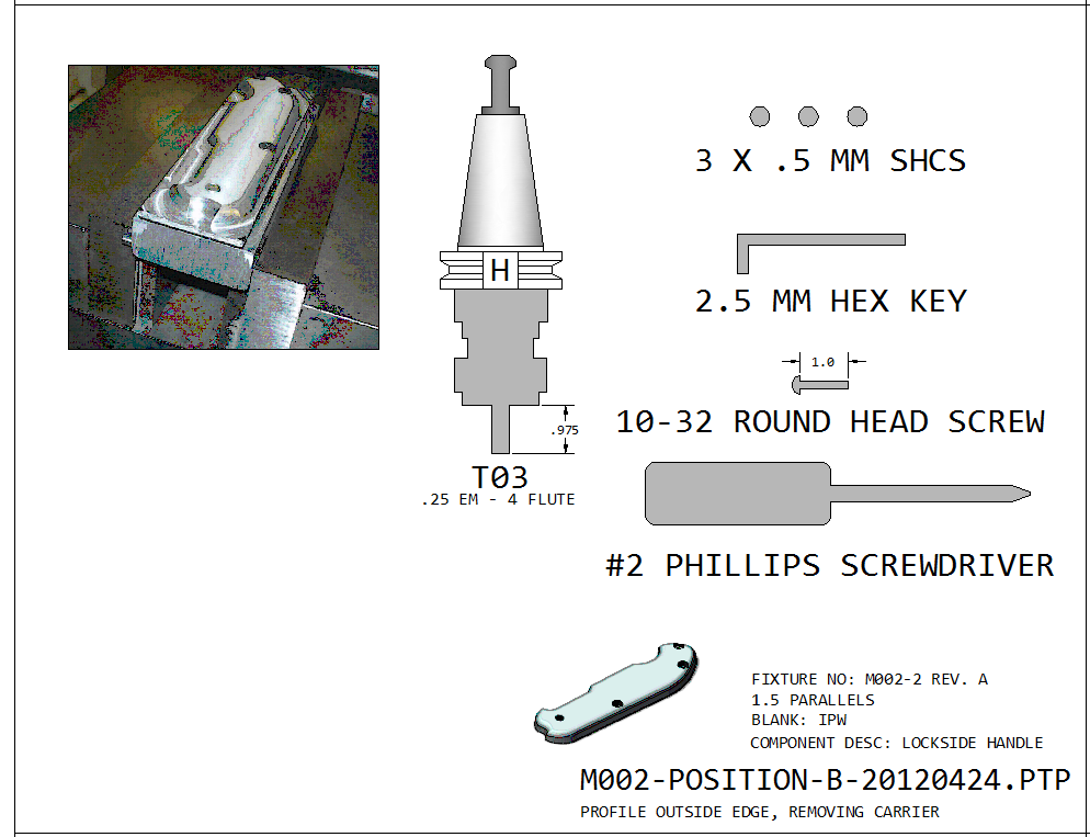
Position B
- Assemble on 002 FXT
- Standard Vise position
- Slide to locating pin
- Use 1.5 parallels
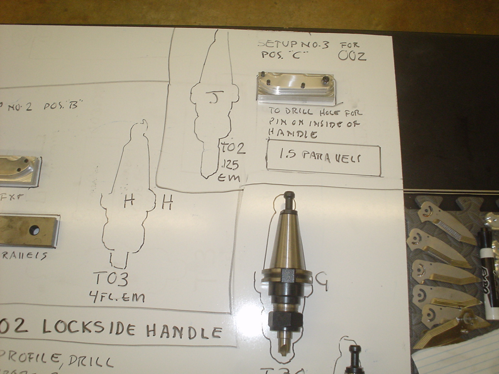
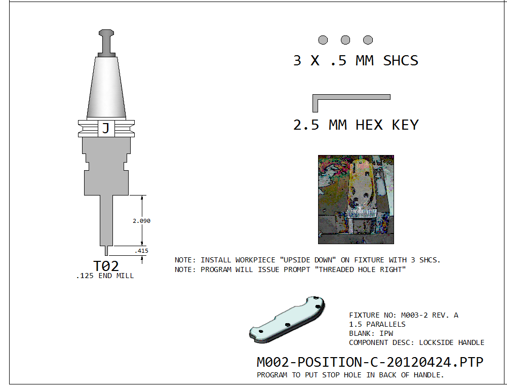
Position C
- Assemble UPSIDE DOWN on 003 FXT (Opposite side fixture)
- Standard Vise position
- Slide to locating pin
- Use 1.5 parallels
Tool Numbers (ref. only) Refer to master list for current details.
CAM Files
CNC Files
Setup 1 – 1.625 parallel, + 0.090 Spacer

002_CNC_1_LocksideHandle_1_profile
Setup 2 – 002 Fixture 1.500 parallel

002_CNC_8_LocksideHandle_2 (omit?)
Setup 3 – Flip over, assemble onto 003 fixture, use 1.500 parallels

002_CNC_LockSideHandle_3_Stop – THD HOLE RIGHT (mill hole for stop pin)
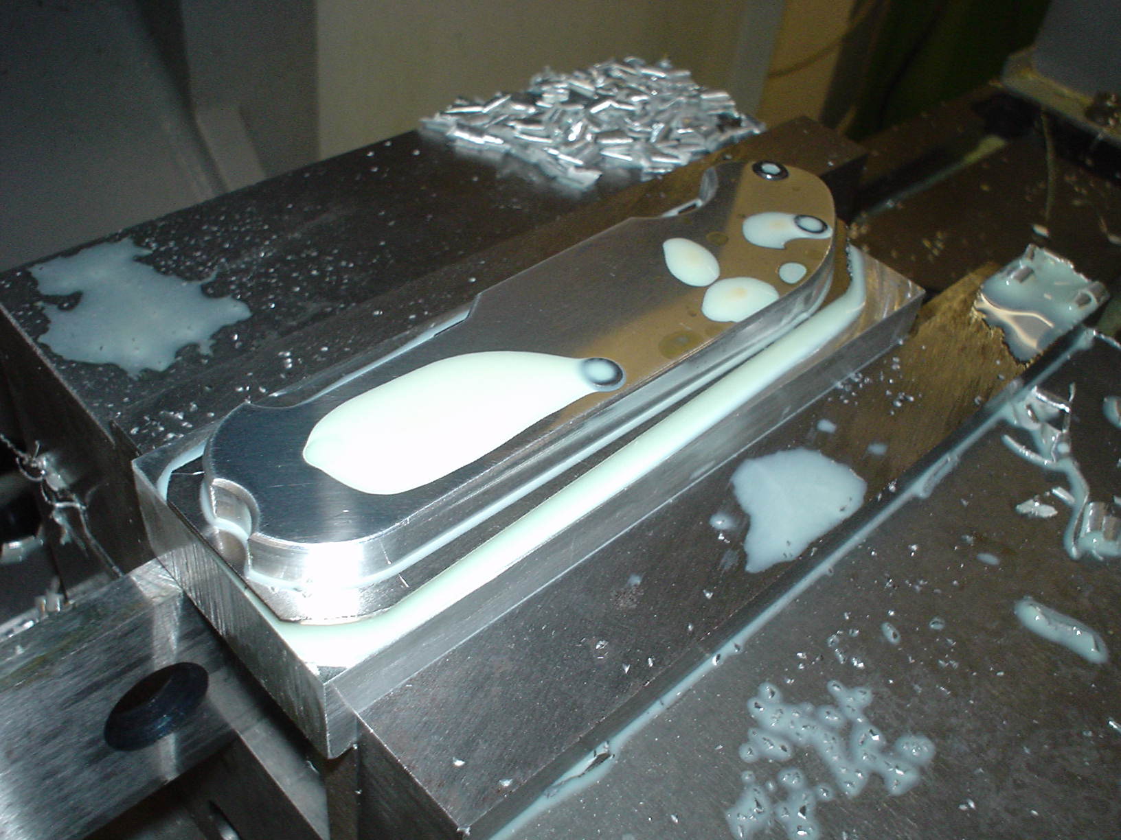
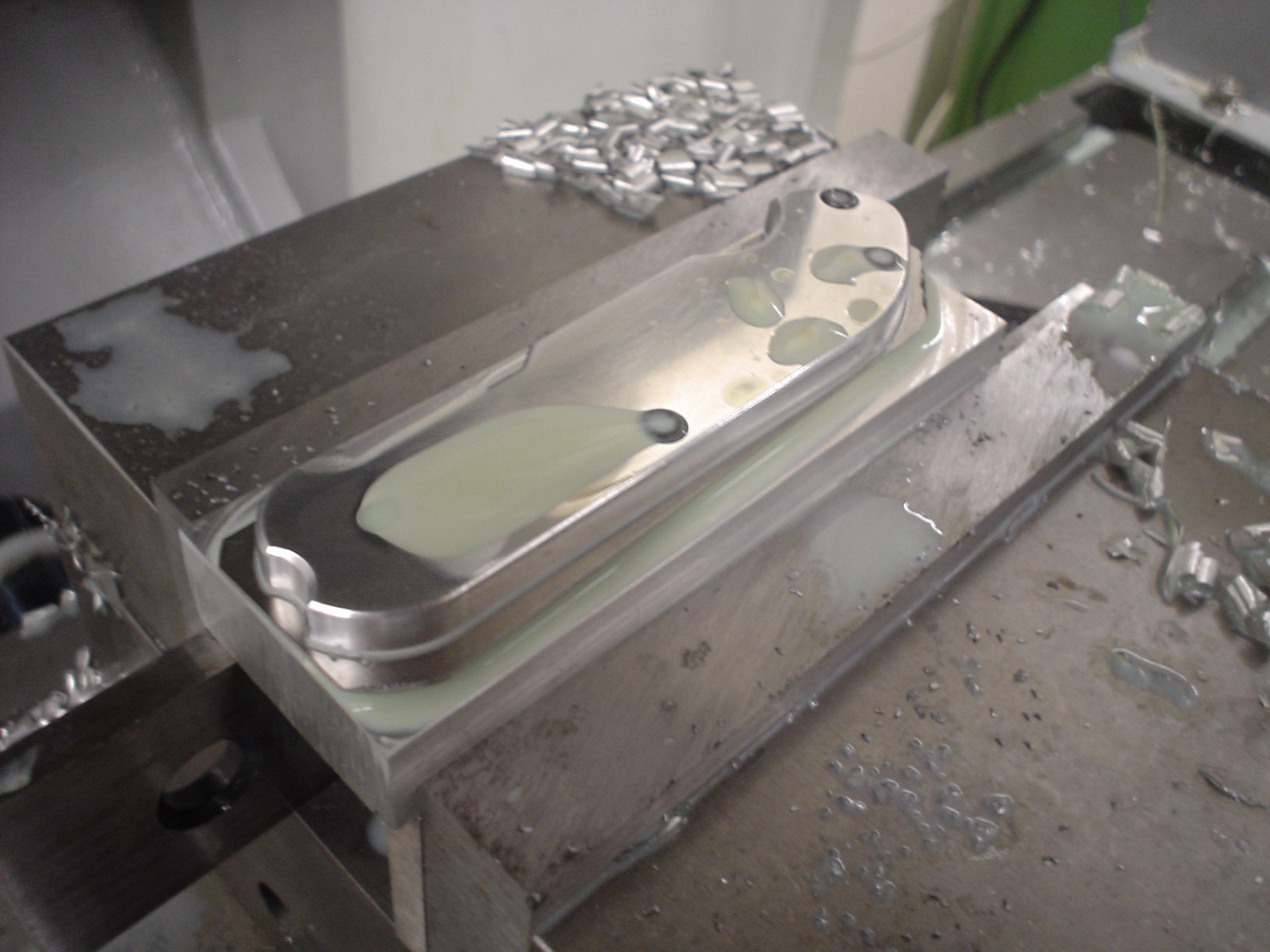
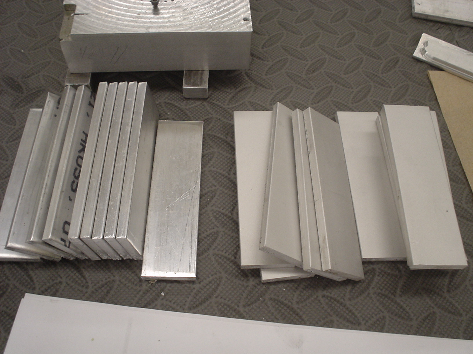
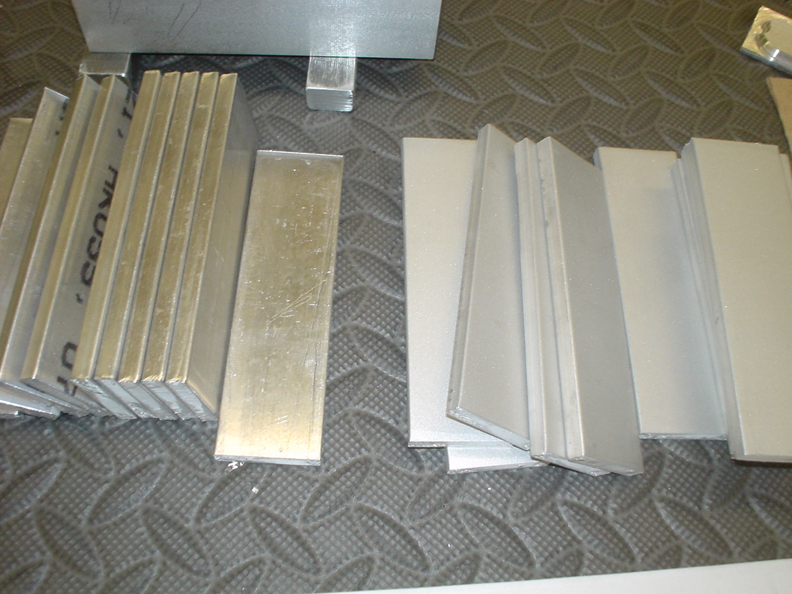
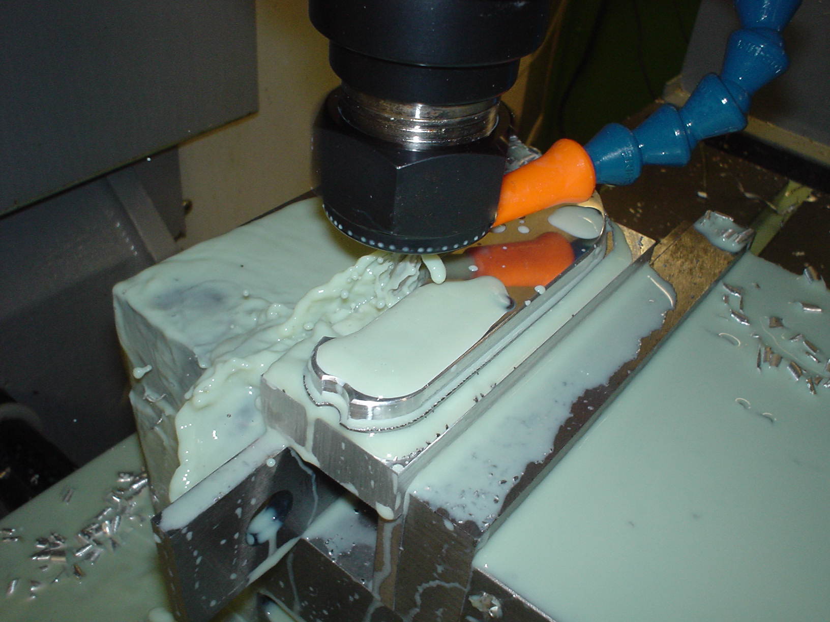
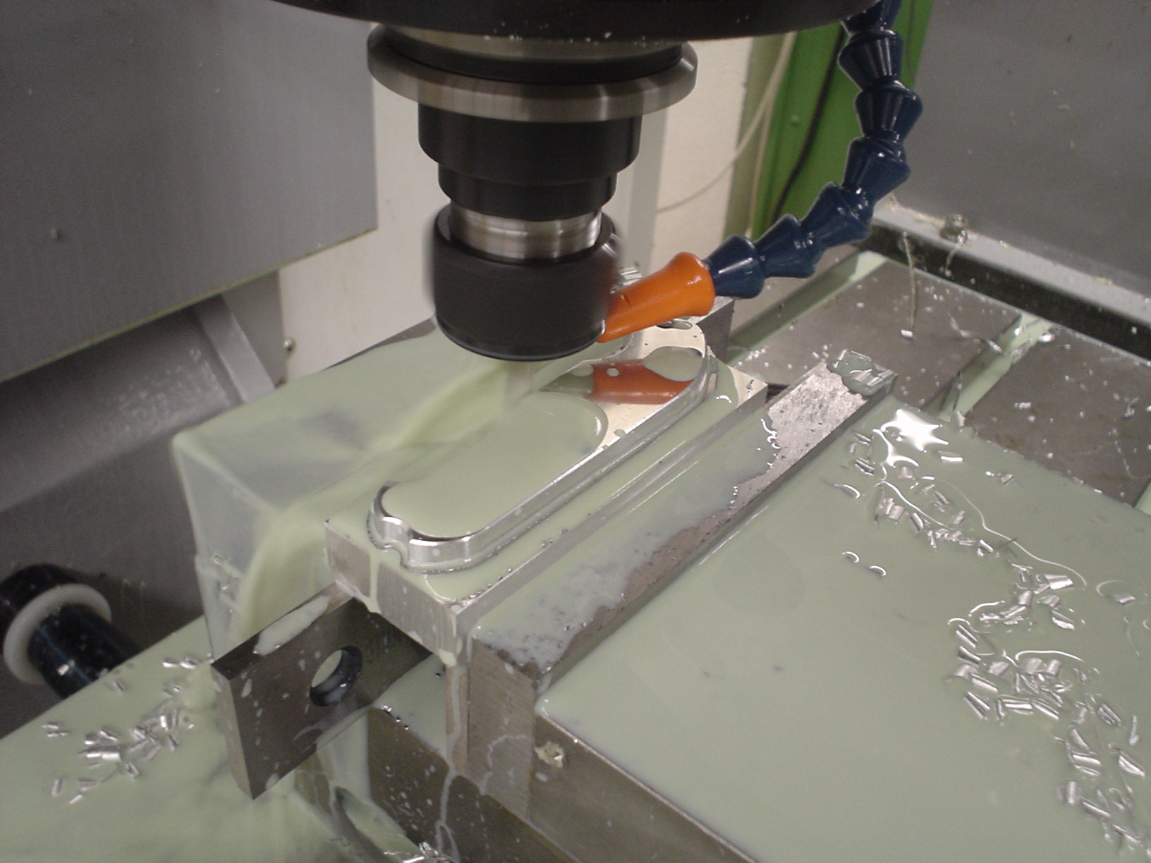
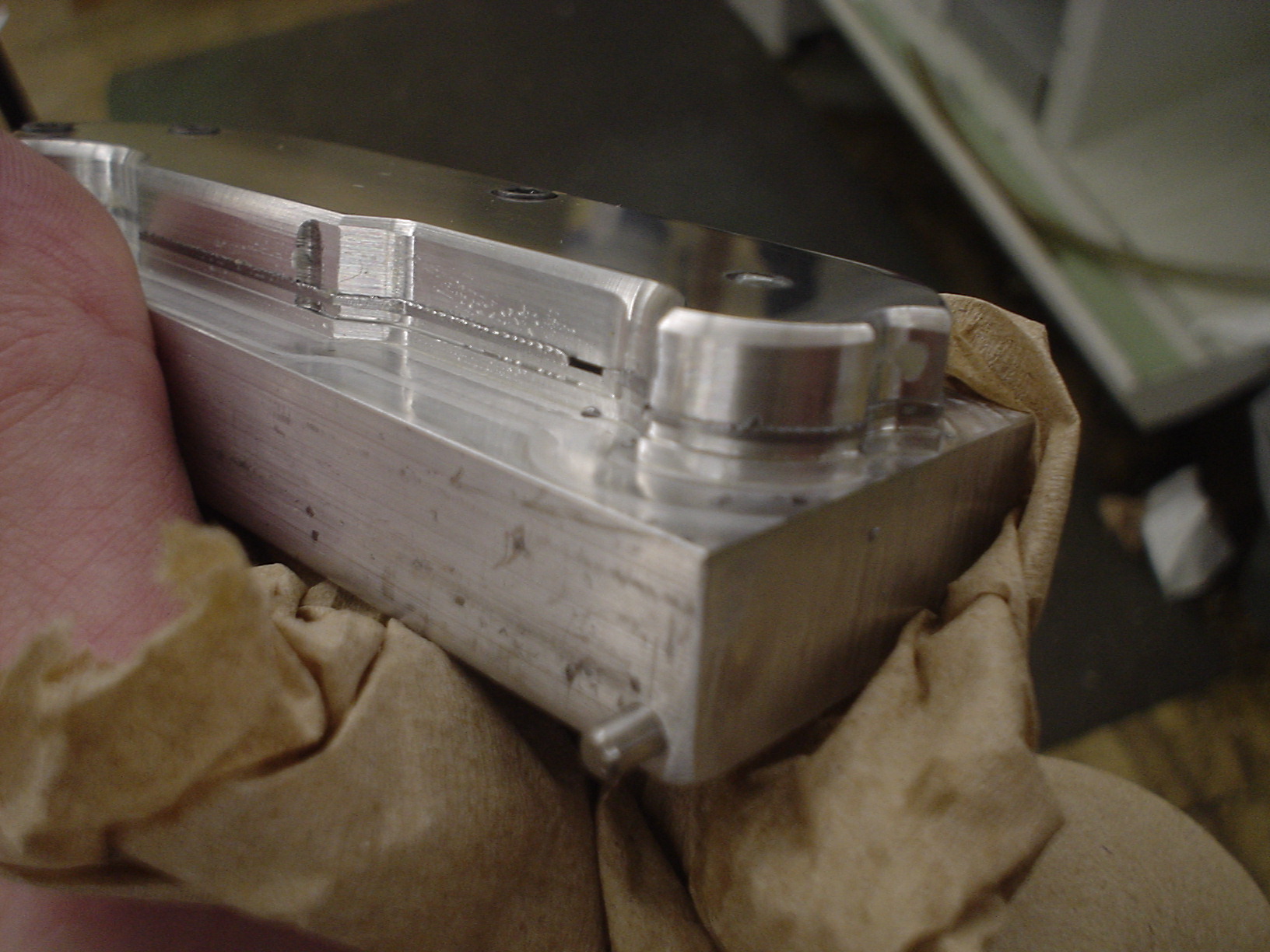
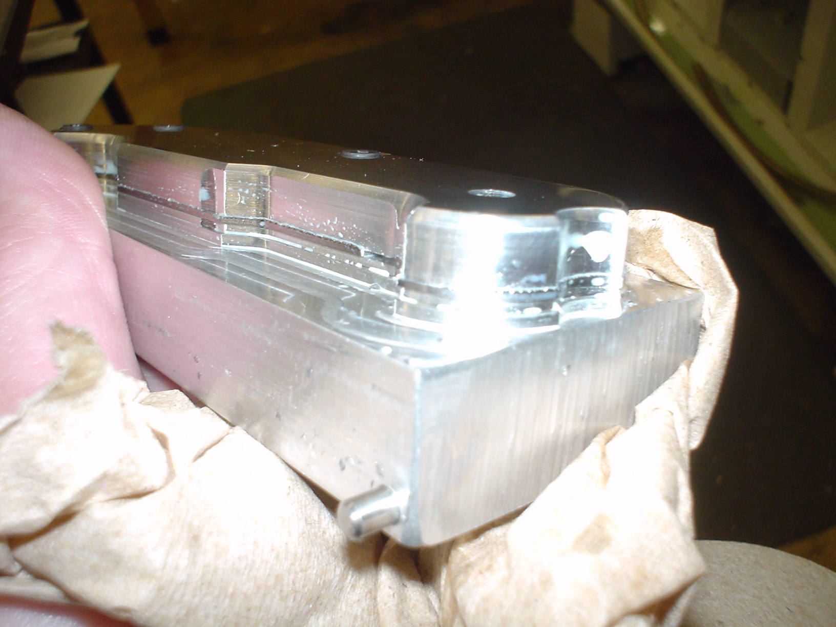
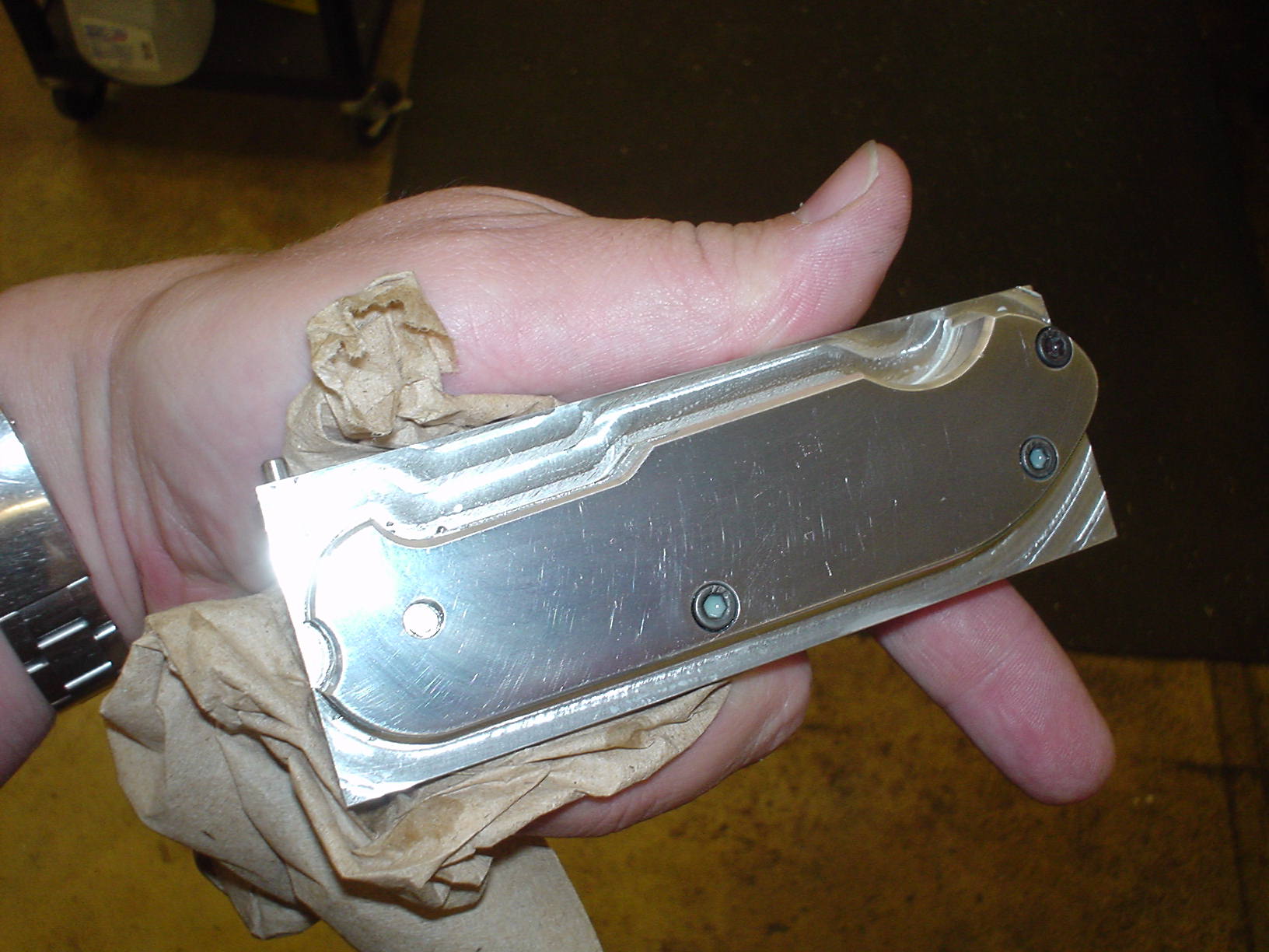
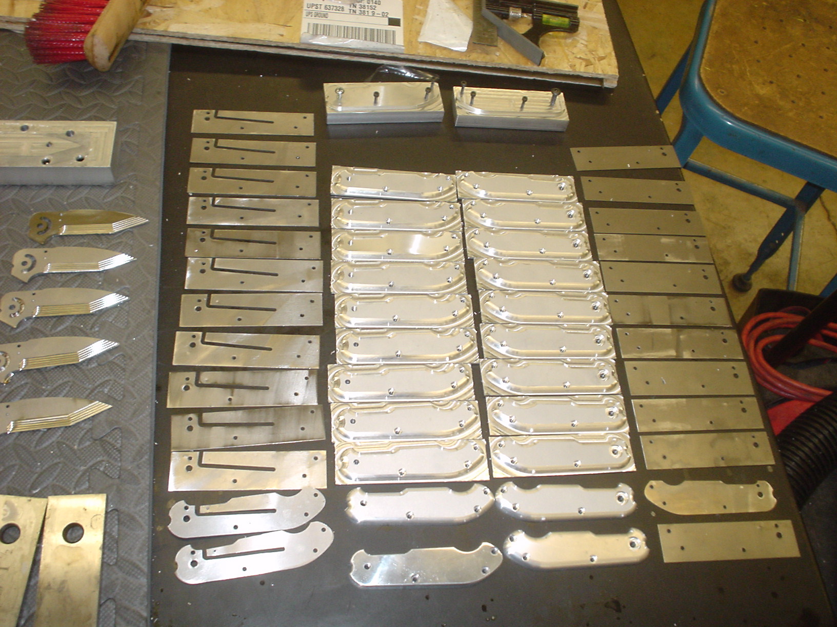
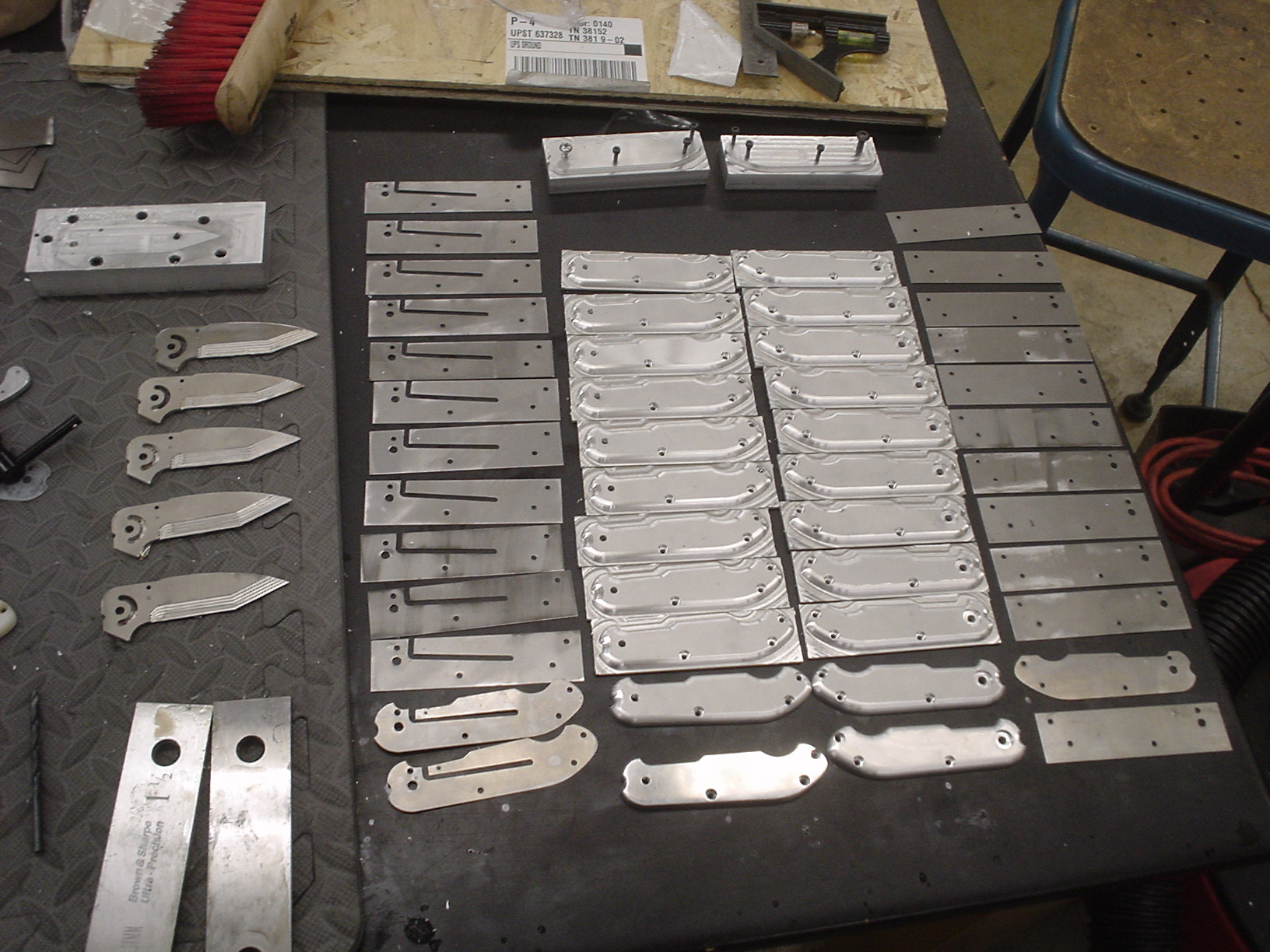
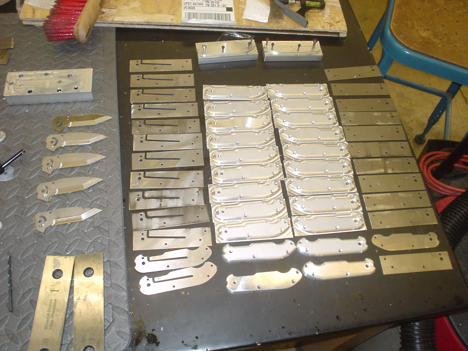
Photos