Circular interpolation at a given feedrate.
G02 Clockwise arc motion at feedrate.
G03 Counterclockwise arc motion at feedrate.
The clockwise direction is determined by viewing the arc from the positive side of a vector normal to the arc plane.
Like the G01 command, G02 and G03 require a feedrate (F) as well as destination (or distance) coordinates (X, Y, and/or Z). The feedrate will default to the current feedrate if it has been commanded previously in the program. For full circles, the X, Y and Z can be omitted (see I, J, K Method below).
The arc must lie parallel to a plane defined by two axes of machine motion. This plane must be set (usually in the program header) by G7, G18, G19.
There are two different ways to program a G02 or G03.:
I, J, K Method
This is the only method that can be used to program a complete circle. It can be used any time the R method could be used, but it is a little more complicated.
Only two of I, J, and K will be used. This will depend on what arc plane has been selected (see by G7, G18, G19).
- G17 – Use I and J
- G18 – Use I and K
- G19 – Use J and K
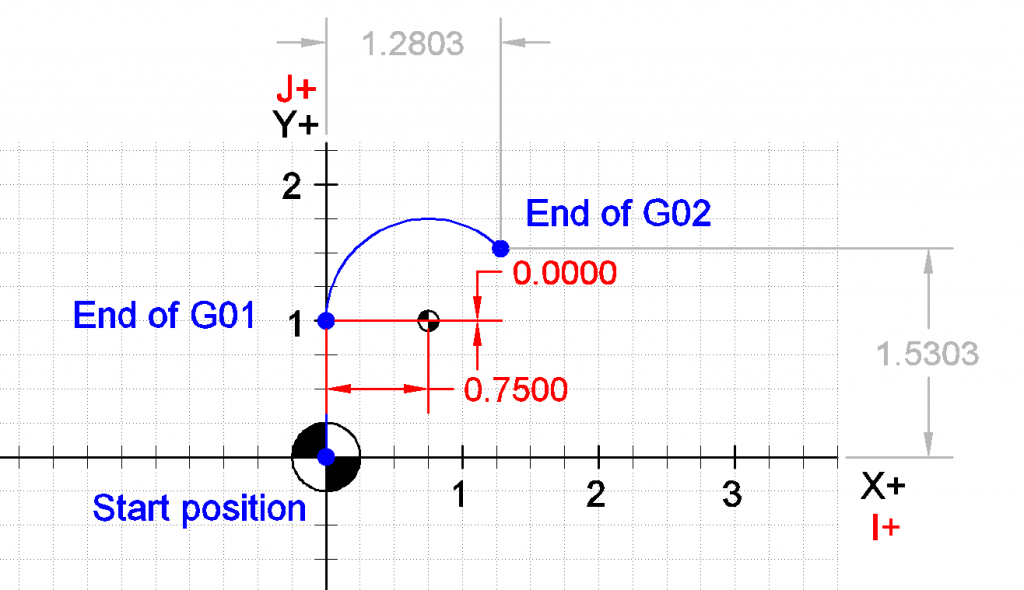
The I, J and K arguments specify the DISTANCE from the ARC START POINT to the CENTER POINT of the arc. Note that the start point of the arc is NOT GIVEN in a G02 or G03 command. The start point is determined by the location of the cutter when the command is implemented. Also, the center point is never given explicitly in the command. I, J, and K are DISTANCES. If the geometry of the circle is impossible (to within .0001), an error is usually thrown.
I, J, K Method Example 1:
Assume the machine is currently at X0.0 Y0.0 and G90 and G17 are enabled in the header.
G01         Y1.0    F8.0;
G02 X1.2803 Y1.5303 I.750;
Will produce the following toolpath. Notice the value for J (the distance in the Y axis) would be zero, it can be omitted:
Note: The value of i is 0.75 because it is that distance from the arc start point, not because it is that distance from the Y-axis.
I, J, K Method Example 2:
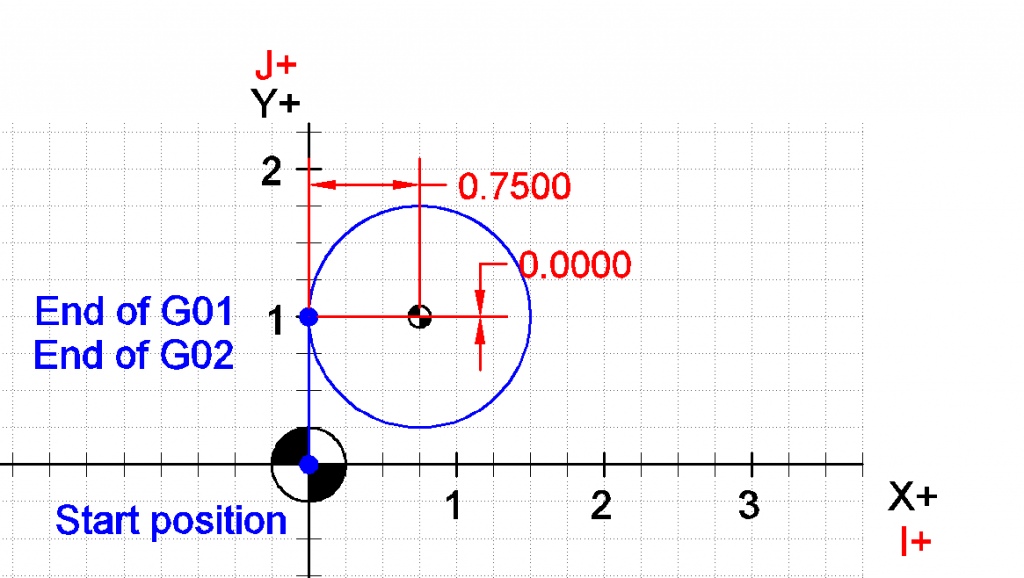
To program a full circle, the end point is omitted from the G02 code. Again, assume the machine is currently at X0.0 Y0.0 and G90 and G17 are enabled in the header:
G01         Y1.0    F8.0;
G02                I.750;
R Method
The R Method can only be used for arcs less than 360 degrees. As you might expect, the R address is used to specify the radius of the arc.
R Method Example 1:
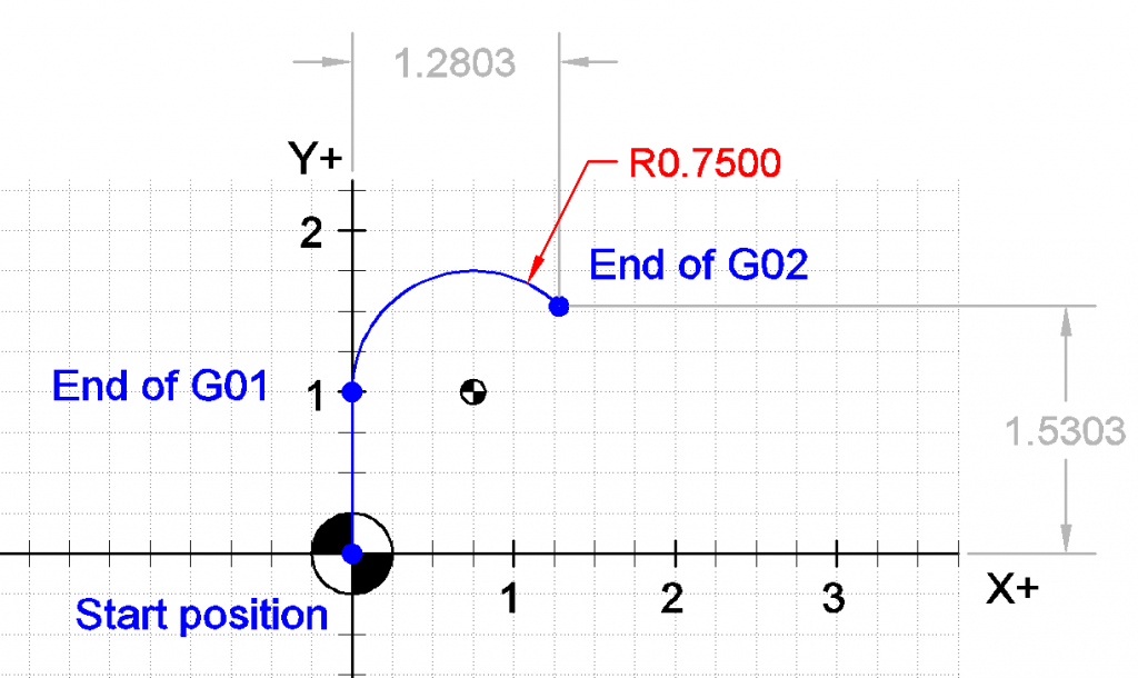
Assume the machine is currently at X0.0 Y0.0 and G90 and G17 are enabled in the header.
G01         Y1.0    F8.0;
G02 X1.2803 Y1.5303 R.750;
R Method Example 2:
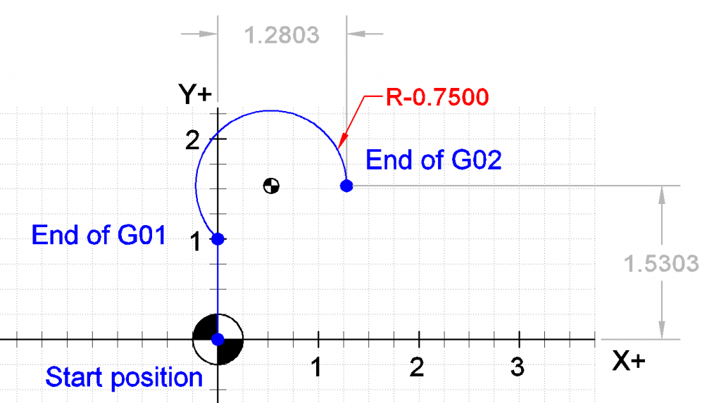
Notice that there is actually another arc that meets the same criteria as the one in the example above. The other arc has a longer arc length but the same radius, start and end points. If we want the arc with the longer arc length, we use a -R value (since -R does not already have a valid meaning).
G01         Y1.0    F8.0;
G02 X1.2803 Y1.5303 R-0.750;
See also: Haas Manual

I want circle program
i love it
The sentence directly below the first diagram should start “Note: The value of I is 0.75 because…”, rather than J. As pointed out in the previous sentence, J = 0 .
domounde programme vilbroquin et arber à came sur la machine 4 axe
please help and e mail me at gmoorewm at gmail dot com. in regards to reply sent.
what would be a good program to get and use for a machinist who is past learning unigraphics and the intense learning the software for what i need.i need a simple program or software that my computer with xp will run i can use to download at home and a workplace for figuring IJK interpolation arcs.trig functions as angle cuts say for example a 6 pointed star.and some creating tool paths for a drawing.or if simple enough draw the part pick points and let the software calculate the m and g codes and the tool paths or rough and finish passes say for a square pocket.something not expensive for a man on disability going back to work maybe part time needed on a part time basis.or will have to manual program whole parts involving much worthless time.