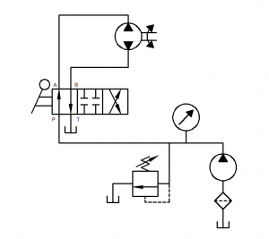
Exercises 1: The basic output motion of a hydraulic system to Hydraulic cylinder.
Objective: To become more knowledgeable with the hydraulic system. The actuator is the general term used for the output device of hydraulic system. Two broad categories are linear actuators that deliver power in a straight line, and rotary actuator that deliver their power in a rotating or circular motion. The linear device is called a hydraulic cylinder. Hydraulic cylinder is linear actuator. This means that the output of a cylinder is a straight-line motion or force. The major function of a hydraulic is to convert hydraulic power into linear mechanical force to perform work or transmit power.
Procedure/ demonstrations:
1. Make sure relief valve #2 is set at 500 Pound per square inch (PSI). Globe valve # 3 is open, Needle valve #4 is closed, and Needle vale #6 is open.
2. At manifold pressure gauge #5 used the hoses connect to direction valve # 7.
3. Two-output gauge from the direction valve # 7 use the hoses connect to hydraulic Motor #14. (Add a hose for drain from motor)
4. Shift direction valve # 7 to center or neutral position.
5. Turn on hydraulic power supply.
6. Shift direction valve # 7 to forward and reverse. We will see motor rotation for two way counter clockwise, and clockwise.
7. Turn off hydraulic power supply.
Discussion: when we shift the direction valve forward or reverse we will see the motor rotation two way there are counter clockwise and clockwise. The torque is the rotational force component of the motor’s output. It is a turning or twisting effort by the output shaft. Motion is not required to have torque, but if the torque is sufficient to overcome any resistance to it, rotary motion will be result. The torque is always present at the drive shaft, but is equal to the load multiplied by the radius. A given load will impose less torque on the shaft if the radius is decreased. However, the large radius will move the load faster for a given shaft speed. Motor speed is a function displacement and the volume of fluid delivered to the motor. Maximum motor speed is the speed at a specific inlet pressure with the motor can sustain for an adequate period of time without damage. Minimum motor speed is the slowest, continuous, smooth rotational speed of the motor output shaft. Slippage is the leakage across the motor or the fluid that moves through the motor without doing any work. Pressure required in a hydraulic motor depends on the torque load and the displacement. A large displacement motor will develop a given torque with less pressure than a small unit. Motors will have maximum pressure rating, which is the highest inlet pressure and, therefore, the highest torque load. The motor can continuously withstand for an adequate period of time without damage. The size and torque rating of a motor is usually expressed in pound inches of torque per 100 PSI of pressure.
Summary: All hydraulic motors have several factors in common. Each type must have a surface area acted upon by a pressure differential. This surface is rectangular in gear and vane motors, and circular in radial and axial piston motors. The surface area in each kind of motor is mechanically connected to an output shaft from which the mechanical energy is delivered. Finally, the porting of the pressure fluid to the pressure must be timed in each type of hydraulic motor in order to sustain continuous rotation. The maximum performance of a motor in terms of pressure, flow, torque output, speed, expected life, and physical configuration is determined by the: Pressure capability of internal and external components, Internal leakage characteristics, and Efficiency of force and power transmittal. Hydraulic motors are rated according to displacement (size), torque capability, speed, and maximum pressure limitations.

