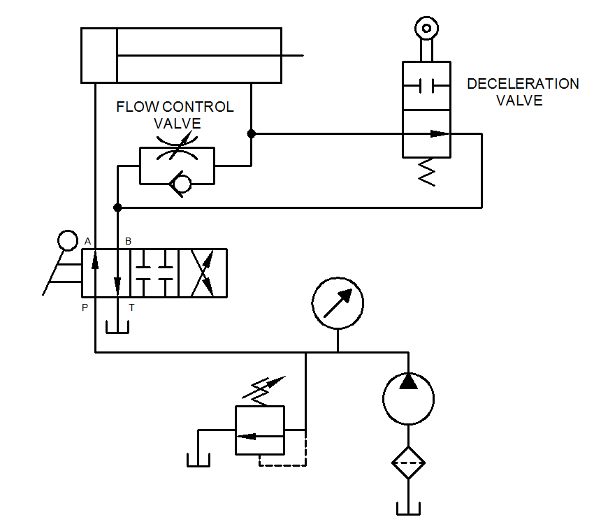
Use a Deceleration valve to by-pass a flow control valve for part of a machine cycle.
Objective: The deceleration valve in this case to become knowledgeable more about the type of the valves for application in the hydraulic system. The hydraulic cylinder often has built-in cushions that slow down the cylinder pistons at the extreme end of theirs travel. An external valve is required when it is necessary to decelerate a cylinder at some intermediate position or to slow down or stop.
Procedure/demonstrations:
1. Make sure relief valve #2 is set at 500 Pound per square inch (PSI). Globe valve # 3 is open, Needle valve #4 is closed, and Needle vale #6 is open.
2. At manifold pressure gage #5 used the hoses connect to direction valve # 7.
3. Two-output gage at the direction valve # 7 use the hoses one connect to flow control valve #10 and deceleration valve # 11 another one connect to extend hydraulic cylinder # 12, then at out put from flow control and deceleration valve # 11 used the hose connect with retract cylinder (in this case we called meter-out circuit).
4. Make sure direction valve # 7 is in center or neutral position.
5. Fully close Flow control valve #10 (counterclockwise rotation of adjusting knob).
6. Turn on power unit.
7. Shift direction valve # 7 to Extend piston rod of # 12
8. The observe pressure on gage # 15 during the piston #12 extension.
9. The piston rod # 12 will be stopped when stem of deceleration valve #11 was depressed by cam on piston rod #12.
10. Open flow control valve # 10 until piston rod moving very slowly. The pressure in #15 is equal to relief valve setting when these are obviously no loads on the piston rod # 12.
11. Shift direction valve # 7 to retract piston rod # 12. The piston rod will return rapidly even though deceleration valve #11 is depressed a portion of the return stroke.
12. Turn off power unit.
Discussion:
The deceleration valve in a typical application above, at a preset point, the valve slows drill head cylinder from rapid advance speed to feed speed. There are exhaust flow from the cylinder passing unrestricted through the deceleration valve. With figure above that a cam mounted on the cylinder rod depresses the valve plunger. Exhaust flow is blocked at the deceleration valve and pass through the flow control valve, which sets the feed speed. The direction valve in this case is reversed to return the cylinder. The plunger is depressed or not, oil from the direction valve passes through the flow control valve.
Conclusion:
The deceleration valve is restricter type flow control. It is usually used in meter-out circuit. Most deceleration valves are cam operator with tapered spool. It is gradually decrease flow to or form an actuator for smooth stopping or deceleration. A normally open valve cuts off flow when a cam depresses its plunger. It may be used to slow the speed of a drill head cylinder at the transition from rapid traverse to feed.