In theory, there are only three regular planes of projection: the vertical, the horizonal, and the profile. Actually, it is presumed that each of these is, as it were, double; there is, for example, one vertical plane for a front view and another for a back view.
We assume, then, a total of six regular planes of projection. A projection on any one of the six is a regular view. A projection NOT on one of the regular six is an AUXILIARY VIEW.
The basic rule of dimensioning requires that a line be dimensioned only in the view in which its true length is projected and that a plane with its details be dimensioned only in the view in which its true shape is represented. To satisfy this rule, we have to create an imaginary plane that is parallel with the line or surface we want to project in its true shape. A plane of this kind that is not one of the regular planes is called an AUXILIARY PLANE.
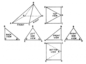
In the upper left of figure 5-22, there is a single-view projection of a triangular block, the base of which is a rectangle.

This block is presumed to be placed for multi-view projection with the right side parallel to the profile plane. The block is then drawn, using all six views of multi-view projection.
By careful examination of figure 5-22, you will see that the lines AB, AE, BD and BC and the surfaces ABC, ABE, and BDE are oblique to three regular planes of projection. The lines are foreshortened and the surfaces are not shown in their true shape in any of the six normal views.
If this part was to be made, say out of sheet metal, the true size and proportions of each face must be established. In this case, an auxiliary view must be projected.
