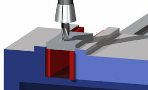
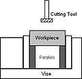
 Parallels are rectangular blocks of metal, commonly made from tool steel, stainless steel or cast iron, which have 2,[1] 4 or 6 faces ground or lapped to a precise surface finish. They are used when machining with a miller, drill or any other machining operation that requires work to be held in a vise or with clamps – to keep work parallel or raised evenly such as in a milling vise to give adequate height for the cutting tool/spindle to pass over.
Contents |
Description
Parallels come in pairs of two, which are machined to be the same dimensions their corresponding faces. They come in a variety of thicknesses and size, allowing them to be stacked up or to support a workpiece which doesn’t have a flat profile. Parallels commonly have a series of holes drilled on the ‘front’ face – allowing them to be used to position a workpiece or secured using t-slot clamps, and a countersink on each side to remove any sharp edges.
Generally, workshop parallels have 4 faces that are machined and ground – the front, back and sides, although some do have the ends with a smooth surface. The surface of a parallel can often tell how it was manufactured, with a ‘grain’ showing that it was ground – and a smooth or mirrored finish showing it has been lapped. Parallels that have a good surface tolerance can be lightly bonded together by sliding or rotating two parallels together, and the smooth surfaces allows a temporary molecular-attraction to take place – this is known as Wringing and is also found with gauge blocks.
Manufacturing
There are two main grades of surface tolerance:[2]
- Grade A – Used for close-tolerance work, such as inspection or precision machining
- Grade B – Lower surface tolerances, and are used for lower-precision machining
Parallels are first machined to rough dimensions, leaving a few millimeters to allow the rest to be ground. Parallels that only have 2 or 4 precision faces will often have the tool-marks from the machining on the non-ground sides. They are then paired and placed in a grinding machine, and each face is ground until the overall dimensions are correct – they are paired during this stage so that even if the dimensions are not correct, they are still parallel to each other. Then, the individual finishes are applied, from drilling to machining a chamfer along the edges to remove any burrs or sharpened edges. They may also be lapped to achieve a mirror smooth surface. Most parallels are also hardened.[1]
Parallels are manufactured to either imperial or metric dimensions, and are often sold in a set, with several pairs of different sizes.[1]
Uses
Parallels are used in machining operations, be it milling, drilling, turning or sometimes grinding. The most common use is to support work when it is in a vise or clamped to the machine bed. If a workpiece is too small to be machined in a vise without it being in contact with all three faces of the vice – parallels can be used either side to give clearance from the vise, and to give support from underneath to eliminate the workpiece being pushed down by the force of the cutting tool.
Parallels of different sizes can be used to support a workpiece that doesn’t have a ‘flat’ surface underneath, or to give clearance when drilling in a vise to stop the drill damaging the vise. Parallels can also be used if the vise itself has a damaged face, which could cause the workpiece to be held insecurely.
Other uses include giving a raised surface when using t-slot clamps and for comparison with a surface or machined face to check the flatness.
See also
Notes
This information originally retrieved from http://en.wikipedia.org/wiki/Parallels_(engineering)
on Monday 17th October 2011 6:38 pm EDT
Now edited and maintained by ManufacturingET.org


