In materials science, creep is the tendency of a solid material to slowly move or deform permanently under the influence of stresses. It occurs as a result of long term exposure to high levels of stress that are below the yield strength of the material. Creep is more severe in materials that are subjected to heat for long periods, and near melting point. Creep always increases with temperature.
The rate of this deformation is a function of the material properties, exposure time, exposure temperature and the applied structural load. Depending on the magnitude of the applied stress and its duration, the deformation may become so large that a component can no longer perform its function — for example creep of a turbine blade will cause the blade to contact the casing, resulting in the failure of the blade. Creep is usually of concern to engineers and metallurgists when evaluating components that operate under high stresses or high temperatures. Creep is a deformation mechanism that may or may not constitute a failure mode. Moderate creep in concrete is sometimes welcomed because it relieves tensile stresses that might otherwise lead to cracking.
Unlike brittle fracture, creep deformation does not occur suddenly upon the application of stress. Instead, strain accumulates as a result of long-term stress. Creep is a “time-dependent” deformation.
The temperature range in which creep deformation may occur differs in various materials. For example, tungsten requires a temperature in the thousands of degrees before creep deformation can occur while ice will creep near 0 °C (32 °F).[1] As a rule of thumb, the effects of creep deformation generally become noticeable at approximately 30% of the melting point (as measured on a thermodynamic temperature scale such as kelvin or rankine) for metals and 40–50% of melting point for ceramics. Virtually any material will creep upon approaching its melting temperature. Since the minimum temperature is relative to melting point, creep can be seen at relatively low temperatures for some materials. Plastics and low-melting-temperature metals, including many solders, creep at room temperature as can be seen markedly in old lead hot-water pipes. Glacier flow is an example of creep processes in ice.
Contents |
Stages of creep

Strain as a function of time due to constant stress over an extended period for a viscoelastic material.
In the initial stage, or primary creep, the strain rate is relatively high, but slows with increasing strain. This is due to work hardening. The strain rate eventually reaches a minimum and becomes near constant. This is due to the balance between work hardening and annealing (thermal softening). This stage is known as secondary or steady-state creep. This stage is the most understood. The characterized “creep strain rate” typically refers to the rate in this secondary stage. Stress dependence of this rate depends on the creep mechanism. In tertiary creep, the strain rate exponentially increases with stress because of necking phenomena.
Mechanisms of creep
The mechanism of creep depends on temperature and stress. The various methods are:
- Bulk diffusion (Nabarro-Herring creep)
- Climb — here the strain is actually accomplished by climb
- Climb-assisted glide — here the climb is an enabling mechanism, allowing dislocations to get around obstacles
- Grain boundary diffusion (Coble creep)
- Thermally activated glide — e.g., via cross-slip
General creep equation
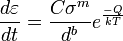
where  is the creep strain, C is a constant dependent on the material and the particular creep mechanism, m and b are exponents dependent on the creep mechanism, Q is the activation energy of the creep mechanism, σ is the applied stress, d is the grain size of the material, k is Boltzmann’s constant, and T is the absolute temperature.
Dislocation creep
At high stresses (relative to the shear modulus), creep is controlled by the movement of dislocations. For dislocation creep, Q = Q(self diffusion), m = 4-6, and b = 0. Therefore, dislocation creep has a strong dependence on the applied stress and no grain size dependence.
Some alloys exhibit a very large stress exponent (n > 10), and this has typically been explained by introducing a “threshold stress,” σth, below which creep can’t be measured. The modified power law equation then becomes:
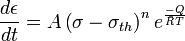
where A, Q and n can all be explained by conventional mechanisms (so 3 ≤ n ≤ 10).
Nabarro-Herring creep
Nabarro-Herring creep is a form of diffusion controlled creep. In Nabarro-Herring creep, atoms diffuse through the lattice causing grains to elongate along the stress axis; k is related to the diffusion coefficient of atoms through the lattice, Q = Q(self diffusion), m = 1, and b = 2. Therefore Nabarro-Herring creep has a weak stress dependence and a moderate grain size dependence, with the creep rate decreasing as grain size is increased.
Nabarro-Herring creep is strongly temperature dependent. For lattice diffusion of atoms to occur in a material, neighboring lattice sites or interstitial sites in the crystal structure must be free. A given atom must also overcome the energy barrier to move from its current site (it lies in an energetically favorable potential well) to the nearby vacant site (another potential well). The general form of the diffusion equation is D = D0exp(E/KT) where D0 has a dependence on both the attempted jump frequency and the number of nearest neighbor sites and the probability of the sites being vacant. Thus there is a double dependence upon temperature. At higher temperatures the diffusivity increases due to the direct temperature dependence of the equation, the increase in vacancies through Schottky defect formation, and an increase in the average energy of atoms in the material. Nabarro-Herring creep dominates at very high temperatures relative to a material’s melting temperature.
Coble creep
Coble creep is a second form of diffusion controlled creep. In Coble creep the atoms diffuse along grain boundaries to elongate the grains along the stress axis. This causes Coble creep to have a stronger grain size dependence than Nabarro-Herring creep. For Coble creep k is related to the diffusion coefficient of atoms along the grain boundary, Q = Q(grain boundary diffusion), m = 1, and b = 3. Because Q(grain boundary diffusion) < Q(self diffusion), Coble creep occurs at lower temperatures than Nabarro-Herring creep. Coble creep is still temperature dependent, as the temperature increases so does the grain boundary diffusion. However, since the number of nearest neighbors is effectively limited along the interface of the grains, and thermal generation of vacancies along the boundaries is less prevalent, the temperature dependence is not as strong as in Nabarro-Herring creep. It also exhibits the same linear dependence on stress as Nabarro-Herring creep.
Creep of polymers

a) Applied stress and b) induced strain as functions of time over a short period for a viscoelastic material.
Creep can occur in polymers and metals which are considered viscoelastic materials. When a polymeric material is subjected to an abrupt force, the response can be modeled using the Kelvin-Voigt model. In this model, the material is represented by a Hookean spring and a Newtonian dashpot in parallel. The creep strain is given by
![\varepsilon(t) = \sigma C_0 + \sigma C \int_0^\infty f(\tau)(1-\exp[-t/ \tau]) \,d \tau](http://upload.wikimedia.org/math/6/6/1/661449a354045627f8c31b199ecc8204.png)
where:
- σ = applied stress
- C0 = instantaneous creep compliance
- C = creep compliance coefficient
- τ = retardation time
- f(τ) = distribution of retardation times
When subjected to a step constant stress, viscoelastic materials experience a time-dependent increase in strain. This phenomenon is known as viscoelastic creep.
At a time t0, a viscoelastic material is loaded with a constant stress that is maintained for a sufficiently long time period. The material responds to the stress with a strain that increases until the material ultimately fails. When the stress is maintained for a shorter time period, the material undergoes an initial strain until a time t1 at which the stress is relieved, at which time the strain immediately decreases (discontinuity) then continues decreasing gradually to a residual strain.
Viscoelastic creep data can be presented in one of two ways. Total strain can be plotted as a function of time for a given temperature or temperatures. Below a critical value of applied stress, a material may exhibit linear viscoelasticity. Above this critical stress, the creep rate grows disproportionately faster. The second way of graphically presenting viscoelastic creep in a material is by plotting the creep modulus (constant applied stress divided by total strain at a particular time) as a function of time.[2] Below its critical stress, the viscoelastic creep modulus is independent of stress applied. A family of curves describing strain versus time response to various applied stress may be represented by a single viscoelastic creep modulus versus time curve if the applied stresses are below the material’s critical stress value.
Additionally, the molecular weight of the polymer of interest is known to affect its creep behavior. The effect of increasing molecular weight tends to promote secondary bonding between polymer chains and thus make the polymer more creep resistant. Similarly, aromatic polymers are even more creep resistant due to the added stiffness from the rings. Both molecular weight and aromatic rings add to polymers’ thermal stability, increasing the creep resistance of a polymer.[3]
Both polymers and metals can creep. Polymers experience significant creep at temperatures above ca. –200°C; however, there are three main differences between polymeric and metallic creep.[4]
Polymers show creep basically in two different ways. At typical work loads (5 up to 50%) ultra high molecular weight polyethylene (Spectra, Dyneema) will show time-linear creep, whereas polyester or aramids (Twaron, Kevlar) will show a time-logarithmic creep.
Applications
Though mostly due to the reduced yield stress at higher temperatures, the Collapse of the World Trade Center was due in part to creep from increased temperature operation.[5]
The creep rate of hot pressure-loaded components in a nuclear reactor at power can be a significant design-constraint, since the creep rate is enhanced by the flux of energetic particles.
Creep was blamed for the Big Dig tunnel ceiling collapse in Boston, Massachusetts that occurred in July 2006.
An example of an application involving creep deformation is the design of tungsten light bulb filaments. Sagging of the filament coil between its supports increases with time due to creep deformation caused by the weight of the filament itself. If too much deformation occurs, the adjacent turns of the coil touch one another, causing an electrical short and local overheating, which quickly leads to failure of the filament. The coil geometry and supports are therefore designed to limit the stresses caused by the weight of the filament, and a special tungsten alloy with small amounts of oxygen trapped in the crystallite grain boundaries is used to slow the rate of Coble creep.
In steam turbine power plants, pipes carry steam at high temperatures (566 °C or 1050 °F) and pressures (above 24.1 MPa or 3500 psi). In jet engines, temperatures can reach up to 1400 °C (2550 °F) and initiate creep deformation in even advanced-coated turbine blades. Hence, it is crucial for correct functionality to understand the creep deformation behavior of materials.
Creep deformation is important not only in systems where high temperatures are endured such as nuclear power plants, jet engines and heat exchangers, but also in the design of many everyday objects. For example, metal paper clips are stronger than plastic ones because plastics creep at room temperatures. Aging glass windows are often erroneously used as an example of this phenomenon: measurable creep would only occur at temperatures above the glass transition temperature around 500 °C (900 °F). While glass does exhibit creep under the right conditions, apparent sagging in old windows may instead be a consequence of obsolete manufacturing processes, such as that used to create crown glass, which resulted in inconsistent thickness.[6][7]
See also
References
- ^ “Rheology of Ice”. http://www.geo.brown.edu/People/Postdocs/goldsby/Icephysics.htm. Retrieved 2008-10-16.[dead link]
- ^ Rosato, et al. (2001): “Plastics Design Handbook,” 63-64.
- ^ M. A. Meyers and K. K. Chawla (1999). Mechanical Behavior of Materials. Cambridge University Press. p. 573. ISBN 978-0-521-86675-0. http://www.toodoc.com/Mechanical-Behavior-of-Materials-ebook.html.
- ^ McCrum, N.G, Buckley, C.P; Bucknall, C.B (2003). Principles of Polymer Engineering. Oxford Science Publications. ISBN 0-19-856526-7.
- ^ Zdeněk Bažant and Yong Zhu, Why Did the World Trade Center Collapse?—Simple Analysis,Journal of Engineering Mechanics, January 2002
- ^ Lakes, Roderic S. (1999). Viscoelastic Solids. p. 476. ISBN 0849396581.
- ^ “Is glass liquid or solid?”. http://math.ucr.edu/home/baez/physics/General/Glass/glass.html. Retrieved 2008-10-15.
Further reading
- Ashby, Michael F.; Jones, David R. H. (1980). Engineering Materials 1: An Introduction to their Properties and Applications. Pergamon Press. ISBN 0-08-026138-8..
- Frost, Harold J.; Ashby, Michael F. (1982). Deformation-Mechanism Maps: The Plasticity and Creep of Metals and Ceramics. Pergamon Press. ISBN 0-08-029337-9..
- Turner, S (2001). Creep of Polymeric Materials. Oxford: Elsevier Science Ltd.. pp. 1813–1817. ISBN 0-08-043152-6..
External links
- Creep Analysis Research Group – Politecnico di Torino
- Deformation-Mechanism Maps, The Plasticity and Creep of Metals and Ceramics
- The National Institute of Standards and Technology – WTC Briefing
- “Introduction to Creep”. Archived from the original on 2008-06-17. http://web.archive.org/web/20080617053739/http://www.nuc.berkeley.edu/thyd/ne161/jlrhoads/creep.html. Retrieved 2008-10-16.
This information originally retrieved from http://en.wikipedia.org/wiki/Creep_(deformation)
on Wednesday 3rd August 2011 9:22 pm EDT
Now edited and maintained by ManufacturingET.org